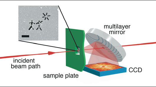
Figure 1. The FEL beam is incident from the left and is focused to a 20-μm spot on the sample. The direct beam passes through the sample window and exits the camera through a hole in a graded multilayer planar mirror. The diffracted light from the sample reflects from that mirror onto a CCD detector. The on-axis path length from the sample to the detector is 55 mm. For our objects and wavelengths this distance is in the far field, where the diffraction pattern is equal to the Fourier transform of the exit wave.
H.N. Chapman1, J. Hajdu2, S. Bajt1, A. Barty1, D. Barsky1, W.H. Benner1, M. Bergh2, M.J. Bogan1, C. Bostedt3, S. Boutet4, C. Caleman2, F. Burmeister2, S. Düsterer5, M. Frank1, S.P. Hau-Riege1, K.O. Hodgson4, M. Hoener3, G. Huldt2, M. Kuhlmann5, R.W. Lee1, R.A. London1, F.R.N.C. Maia2, S. Marchesini1, E. Marklund2, Th. Möller3, E. Plönjes5, U. Rohner1, J.R. Schneider5, M.M. Seibert2, D.A. Shapiro6, E. Spiller1, D. van der Spoel2, A. Szöke1, N. Timneanu2, R. Treusch5, Th. Tschentscher5, and B.W. Woods1
1 Lawrence Livermore National Laboratory, 7000 East Ave., Livermore CA 94550, USA.
2Laboratory of Molecular Biophysics, Uppsala University, Husargatan 3, Box 596, SE-75124 Uppsala, Sweden.
3Institut für Optik & Atomare Physik, T. U. Berlin, Hardenbergstraße 36, PN 3-1, 10623 Berlin, Germany.
4Stanford Synchrotron Radiation Laboratory, SLAC, 2575 Sand Hill Road, Menlo Park, California 94305, USA.
5Deutsches Elektronen-Synchrotron, DESY, Notkestraße 85, D-22607 Hamburg, Germany.
6CBST, University of California, Davis, 2700 Stockton Blvd., Suite 1400, Sacramento, CA 95817, USA
Published in: Nature Physics 2, 839 (2006)
Using the FLASH facility we have demonstrated high-resolution coherent diffractive imaging with single soft-X-ray free-electron laser pulses [1]. The intense focused FEL pulse gives a high resolution low-noise coherent diffraction pattern of an object before that object turns into a plasma and explodes. Our experiments are an important milestone in the development of single-particle diffractive imaging with future X-ray free-electron lasers [2,3]. Our apparatus provides a new and unique tool at FLASH to perform imaging of biological specimens beyond conventional radiation damage resolution limits [2, 4] and to acquire images of ultrafast processes initiated by an FEL pulse or other laser pulse.
Coherent diffractive imaging is an ideal method for high-resolution ultrafast imaging with an FEL. Since no optical element is required, the method can in principle be scaled to atomic resolution with short enough wavelength. Spatial and temporal coherence are necessary to ensure that the scattered light waves from all positions across the sample are correlated when they interfere at the detector, giving rise to a coherent diffraction pattern that can be phased and inverted to give a high-resolution image of the sample. In contrast to crystals, where scattering from the many unit cells constructively interfere to give Bragg spots, the coherent diffraction pattern of a non-periodic object is continuous. Such a coherent diffraction pattern contains as much as twice the information content of the pattern of its crystallized periodic counterpart—exactly the amount of information needed to solve the phase problem and deterministically invert the pattern to yield an image of the object [5, 6]. The computer algorithm that performs this function replaces the analogue computations of a lens: summing the complex-valued amplitudes of scattered waves to form an image at a particular plane.
Our experimental geometry is shown in Fig.1. We focus a coherent X-ray pulse from the FLASH source onto the sample and record the far-field diffraction pattern of the object on an area detector (a direct-detection CCD chip) centered on the forward direction. The CCD is protected from destruction by the intense forward scattered beam by a mirror that reflects only the diffracted light onto the detector; the direct beam harmlessly passes through a hole in the mirror. The mirror is coated with a resonant X-ray multilayer coating. We fabricated the coating so that the layer period varies across the mirror in such a way that only in-band X-rays propagating from near the sample interaction point are efficiently reflected. In this way the mirror is a very effective filter that rejects noise such as broadband emission from the sample (e.g. when it turns into a plasma and explodes) and offaxis stray light from scattering and emission of beam line components. This arrangement was crucial here to record clean single-pulse diffraction patterns that could be phased and inverted.
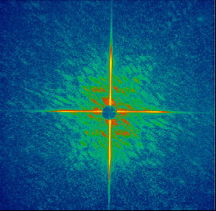
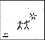
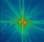
The coherent flash diffraction pattern of an object is shown in Fig. 2 (a). This pattern was recorded with a single 25 fs FEL pulse focused to a peak intensity of (4±2)x1013 W/cm2 on the sample. The pattern extends to a diffraction angle of 15° at the midpoint of its edge (corresponding to a momentum transfer of 8.1 μm-1). The object was a micron-sized pattern cut through a silicon nitride membrane with a focused-ion beam (FIB) as shown in the insert of Fig. 1. We estimate that the absorbed energy density was approximately 20 eV/atom in the silicon nitride and that the sample reached a temperature of about 60,000 K before vaporizing. A second diffraction pattern taken 20 s after the first exposure shows diffraction from a hole left in the membrane caused by the first pulse (see Fig. 2 c). That is, the first pulse utterly destroyed the sample but not before a diffraction pattern of the apparently undamaged object could be recorded.
Figure 2 (b) shows the image of the object reconstructed from the diffraction pattern of Figure 2 (a). Image reconstruction was performed using our iterative transform algorithm, Shrinkwrap [6]. This algorithm solves the phase problem without requiring a priori knowledge about the object. The phases that are retrieved are combined with the Fourier magnitudes that were measured in the coherent diffraction pattern, to invert the pattern to give an image. During the iterations we did not constrain the intensity or phase in the region in the mirror hole, which contains the unrecorded zero spatial frequency, nor did we constrain the object to be real or positive. The recovered image has a resolution of 62 nm, and features of 50 nm (e.g. the belt of the left figure) can be seen. We have obtained even higher resolution at a wavelength of 13.5 nm.
We have imaged many other samples via this method, and are using this technique to perform time-resolved imaging to validate models of the damage processes of particles irradiated by intense FEL pulses.
This work was performed under the auspices of the U.S. Department of Energy by University of California, Lawrence Livermore National Laboratory under Contract W-7405-Eng-48.
| References |
|
[1] H. N. Chapman et al., Nature Phys. doi:10.1038/nphys461 (2006) |


