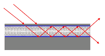
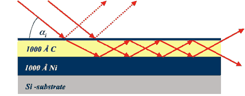
Fig. 1: Sketch of a hard x-ray waveguide consisting of a low density guiding
layer (e.g. Carbon) sandwiched in between layers of higher density (e.g. Ni).
F. Pfeiffer, U. Mennicke, T. Salditt
Experimentalphysik, Universität des Saarlandes, Im Stadtwald 38, Postfach 15 11 50, D-66041 Saarbrücken, Germany
Structural information on thin macomolecular and biomolecular films is hard to obtain. Scattering of hard x-rays offers the advantage of high resolution along all three dimensions. However, scattering intensities are often low due to a small scatting volume, small contrast and low degree of order. A new approach which may help to boost the signal to noise ratio is presented by Pfeiffer et al., by integrating a thin film composed of about ten lipid bilayers on silicon into a resonant x-ray structure or x-ray waveguide. In such a structure the sample itself makes up the waveguiding media with a a local field enhancement which can theoretically reach two orders of magnitude. This resonant field distribution is then used as a primary wave for grazing incidence diffraction, allowing the researches to observe lateral structural features of the lipid chain ordering, which would be hardly observable whithout the use of the x-ray resonances, when using comparable instrumental conditions.
X-ray waveguide structures are currently developed, which may significantly extend the conventional methods of x-ray analysis. The combination of novel x-ray sources and optical elements may lead to x-ray beams with nanometer sized cross sections and still enough photons to perform nano-beam x-ray spectroscopy, diffraction or imaging experiments [1-6]. X-ray waveguides can be obtained from thin film structures consisting of a low density guiding layer sandwiched in between layers of higher electronic density [7]. In such a system, guided modes can resonantly be excited by shining a plane wave onto the waveguide under grazing incidence at a set of discrete angles αi,n, as was first demonstrated by Sinha and coworkers [1], see Fig. 1. A coherent beam exits the structure at the side with a cross section corresponding to the thickness of the guiding layer. Typical beam sizes range in between 2000 Å and 500 Å, but 100 Å have also been achieved, as reported previously [6].
At the same time, the local field intensity in the guiding layer can be increased by up to two orders of magnitude with respect to the incident field. In a recent experiment carried out at the D4 bending magnet station of HASYLAB, we used a x-ray waveguide to observe the diffraction signal of a biomolecular thin film at highly enhanced signal to noise ratios. For this application, the biomolecular sample was directly incorporated in the waveguide structure. Thus, the sample itself makes up the waveguiding medium, rather than being illuminated at the exit of the waveguide. In the same spirit, Zwanenburg et al. have previously studied the mode mixing pattern at the exit of a waveguide structure and used this pattern to determine structural properties of a colloidal suspension held in between two silicon wafers [5].
In particular, we have used the scattering geometry of grazing incidence diffraction under resonance conditions to study organic thin film structures, namely phospholipid membranes (1,2-dimyristoyl-sn-glycero-3-phosphatidylcholine, DMPC). The samples have been incorporated directly into a waveguide structure thus formed by a silicon substrate, ten bilayers of DMPC and an evaporated Ti cap layer. Importantly, we point out that nearly any combinations of organic and in particular biomolecular thin filmswith a thickness larger than about 10 nm sandwiched in between inorganic layers (silicon, glass, transition metals) fulfill the optical criteria of a x-ray waveguide, and that structural information on the molecular level can be extracted with unprecedented signal-to-noise ratios.
To fabricate the first resonant beam coupling device with an incorporated biomolecular film, we made use of a novel technique to prepare highly aligned and morphological intact lipid bilayers on solid surfaces, which has recently been developed in our laboratory [8]. After cleaning and plasma etching of standard commercial silicon wafers, lipid solutions (10 mg/ml DMPC in Isopropanol) were spin-coated on the hydrophilized substrates, resulting in thin wetting films. Subsequent to fast solvent evaporation, a well defined number N of bilayers nucleates at the silicon surface. After putting the samples in vacuum over night, the film can be hydrated in controlled water vapor atmospheres for analysis or further processed. In our case, thin metal layers (Ti, Cr or NiCr) were grown on the top bilayer by a slow, thermal evaporating process.
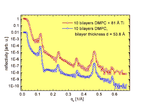
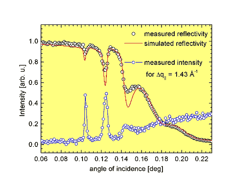
The x-ray experiment was carried out at the bending magnet beamline D4 at HASYLAB/DESY. Higher energies were cut by a horizontal Rh mirror to reduce the heat load on the Si(111)-monochromator, which was adjusted to an x-ray energy of 12.5 keV. Fig.2 shows the reflectivity curve of ten DMPC bilayers deposited on a silicon substrate, both with (top) and without (bottom) additional cap layer composed of evaporated Ti. The curves have been corrected for diffuse background and illumination effects and are shifted vertically for clarity. They clearly demonstrate two major results: Firstly, the film structure remains largely unchanged after the additional metal evaporation, as proven by the similarity of the curves. Secondly, the multilamellar stack forms a uniform homogeneous film of ten bilayers as indicated by the nine minima in between the Bragg peaks (Kiessig fringes). Importantly, zooming into the region of total external reflection of the capped sample, characteristic sharp cusps are observed, indicative of the resonant modes [9,10], see Fig. 5 for a close-up on linear scale.
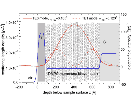
To quantitatively analyze the observed resonance effects, we have calculated the internal (and external) standing wave field as a function of the structural and geometric parameters (layer-thickness, composition and density, interface roughness, angles of incidence, x-ray energy) by a transfer matrix algorithm similar to the one used in the case of optical waveguides . Fig. 3 shows the calculated field distribution |Ey(z)|2 as a function of distance z below the surface. The guiding layer comprises the ten bilayers with dDMPC = 10 x dbl= 538 Å. Importantly, the intensity gain compared to the incident beam reaches a factor of ~ 120.
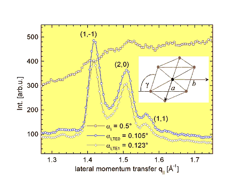
To demonstrate the concept of waveguide-enhanced scattering, we studied the lateral hydrocarbon chain ordering under simultaneous excitation of modes. For this purpose, grazing incidence diffraction (GID) scans have been performed, varying the scattering angle 2q in the plane of the bilayers to intersect the crystal truncation rods corresponding to the 2D Bragg reflections of the hydrocarbon chain lattice.
The relatively small scattering volume of about ten DMPC bilayers was not sufficient to overcome the relatively high background level due to limited beam brilliance at the D4 bending magnet station. However, the situation changed dramatically after adjusting ai exactly to the values of TE0- or TE1-mode excitation. The corresponding two curves are shown in Fig. 4 (circles and diamonds). Only for these two discrete angles, the resonantly enhanced wavefield at the position of the DMPC bilayers (guiding layer), along with the efficient background suppression due to the exponentially decaying electric field in the substrate, resulted in the observability of the 2D Bragg reflections.
The three observed peaks can be indexed to an 2D hydrocarbon chain lattice [11] with sublattice constants a = 4.907 Å, b = 8.39 Å, and an angle g = 96.3o representing a slight distortion with respect to the face-centered orthorhombic subcells (space group 62, Pbnm) often encountered in lipid gel phases (see also the insert in Fig. 4). Furthermore, it was interesting to see, that the metal capped bilayers could still be swollen in water vapor and heated above the main phase transition of DMPC.
These resonance enhanced diffraction effects are most clearly evidenced by the curves shown in Fig. 5 (full circles connected by line), where the detector is kept at a fixed 2q position corresponding to the (1,-1) reflection at q|| = 1.43 Å-1, while αi is scanned in a range where the modes are excited. The scattered intensity peaks sharply at the angles of αi,TE0 = 0.105o and αi,TE1 = 0.123o, respectively. These angles correspond to the mode-excitation, as can not only be seen from simulations, but also directly from a comparison to the reflectivity curve with the characteristic cusps (experiment: open symbols, simulation: straigth line) [10]. Contrarily, under off-resonance conditions, a level of residual scattering (background) is observed, which increases with αi due to the correspondingly increasing values of the penetration depth.
In summary, we have successfully demonstrated that the resonant x-ray beam coupling principle can be applied to structural studies of organic or biomolecular thin film samples. In this approach the samples are directly incorporated in the waveguide. The resonantly enhanced diffraction signal can then be measured by tuning the incidence angle to a resonant mode of the waveguide. Waveguide-enhanced scattering from various macromolecular and supramolecular structures, ranging from synthetic polymers to two-dimensional protein crystals, can thus be envisioned.
Acknowledgments
Part of this work was supported by DFG SFB-486. We thank Jens Als-Nielsen, Dimitri Novikov and the staff of HASYLAB/DESY for providing excellent working conditions at the D4 -beamline.
| References |
|
[1] Y.P. Feng, S.K. Sinha, et al., Phys. Rev. Lett. 71, 537 (1993). |
| Contact information |
|
T. Salditt |
| Further Information |


