

In the course of the FLASH2020+ project, an afterburner undulator will be installed downstream of the present FLASH2 SASE undulators. It will provide circularly polarized light in a wavelength range between 1.33 nm and 1.77 nm (890-700 eV) to widen the spectral range to the L-edges of Fe, Co, and Ni and allow for related research in the field of nanomagnetism.
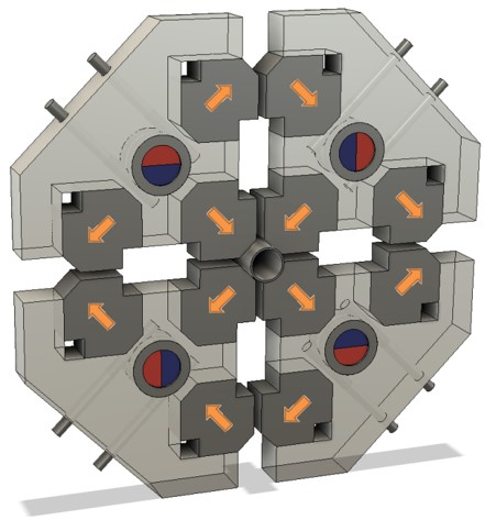
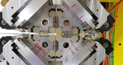
In the APPLE-III configuration, the magnet structure consists of four permanent magnet arrays in Halbach configuration, where the B magnets of the inner arrays around the circular beam pipe are transversely magnetised with their easy axis along the 45° direction as sketched in the figure on the right. The outer arrays form the force compensation scheme and need to be implemented between both, top and bottom girder and also between rows on each girder. Our calculations show that a reduction of magnetic forces by roughly a factor of eight is obtained in this design. Further, a rotatable correction magnet located in each keeper behind the function magnet (red and blue in the right figure) and magnetised across the diameter was intended for tuning of the magnet structure. Following this scheme, a short prototype structure with a period length of 16 mm has been designed and constructed. The force compensation scheme was proven to work successfully as all the sub-girders were moving easily and smoothly in different configurations during manual test performances. Magnetic measurements of the prototype revealed that a period length of 16 mm did not allow for the desired maximum field when also accounting for errors and tuning. In consequence, the required wavelength range would not be reached. We have, therefore, decided to increase the period length to 17.5 mm for the final version that will now be built.
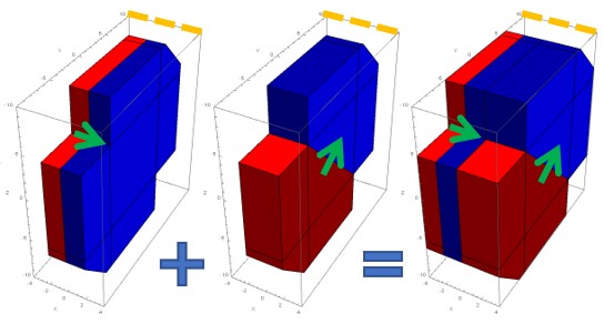
Two types of magnets, commonly named A and B, are used to build the APPLE-III magnetic structure: Type A is magnetised along the short edge, while type B is magnetised along the diagonal of the large plane. In order to improve stability and to simplify the mechanical design, magnets of type A and B are glued together in pairs as shown in the bottom picture on the right. Both types are made from transversely dye-pressed (TP) material with Br,min=1.32 T and Hcj,min=21 kOe. For magnet type B, first, larger magnets which are magnetised along the long edge are pressed and then wire-cut to the desired shape and dimensions.
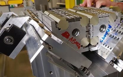
The full-length APPLE-III undulator is presently in construction and will be installed and commissioned in 2023. It will also serve as a full-length prototype for a series of helical IDs to be built within the seeding upgrade of FLASH 1.
Contact: M. Tischer, K. Götze, P. Neumann, A. Schöps, S. Telawane and P. Vagin
Further literature:
Bahrdt J, Frentrup W, Gaupp A, Kuske B, Meseck A, and Scheer M 2004 Proc. SRI Conference 2003 AIP CP 705 215‒18
Liang X, Calvi M, Kittel C, Sammut N J, and Schmidt T 2019 Proc. FEL'19 541‒544
Bahrdt J and Grimmer S 2019 Proc. SRI Conference 2018, AIP CP 2054 030031-1‒6

Loading menu, please wait..
Deutsches Elektronen-Synchrotron DESY
A Research Centre of the Helmholtz Association
✖
Loading menu, please wait..
Loading menu, please wait..
Magnet structure of APPLE-type undulators
Data Privacy Policy |
Declaration of Accessibility |
Imprint
© 2025 Deutsches Elektronen-Synchrotron DESY