


APPLE is an abbreviation for Advanced Planar Polarized Light Emitting undulator. These devices allow for a variable polarization of the emitted soft X-rays, for example, switching between linear and circular polarization. The subgirders on which the magnets are mounted can be moved along the beam axis with respect to each other and vertically away from the beam. This poses challenging requirement for the mechanical construction.
PETRA III
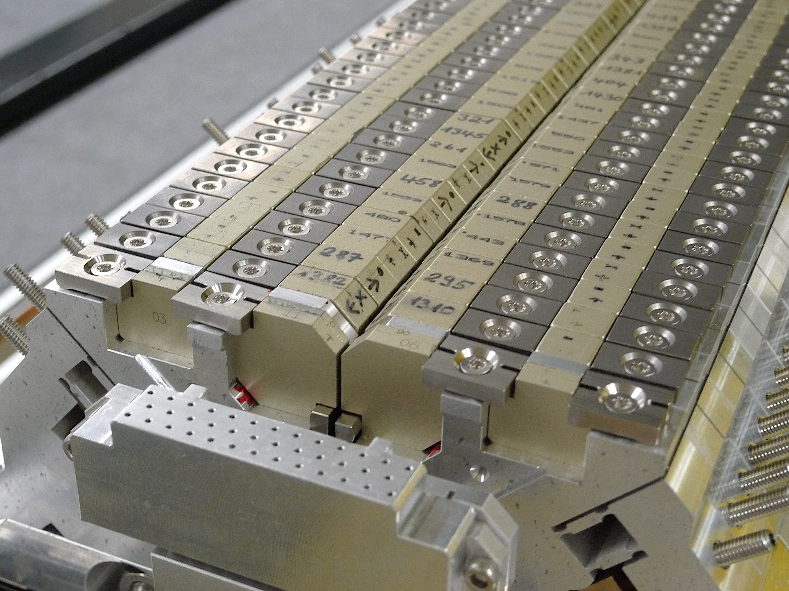
The UE65 device in PETRA III is an APPLE-II device with period length 65.6 mm and a minimum gap of 11 mm. It was built by BESSY (Berlin). Its main parameters can be found here. Due to the strong 3D forces in some modes of operation, a sophisticated mechanical layout is required. The support structure is made from a single piece of cast iron. The aluminium-girders for the magnetic structure are milled from solid blocks in order to avoid the welding of aluminium. The magnet girders are supported at four locations using two cross bars inside each of the girders to minimize the deflection under magnet load. The achieved residual bending is only ±2μm. All four magnet rows can be moved which permits a rotation of the linear polarization vector in the inclined mode by 180°. Due to the large longitudinal force on the magnet rows of up to 58 kN the rows are split longitudinally and each subassembly is driven by an individual screw.
The UE65 device in PETRA III is an APPLE-II device with period length 65.6 mm and a minimum gap of 11 mm. It was built by BESSY (Berlin). Its main parameters can be found here. Due to the strong 3D forces in some modes of operation, a sophisticated mechanical layout is required. The support structure is made from a single piece of cast iron. The aluminium-girders for the magnetic structure are milled from solid blocks in order to avoid the welding of aluminium. The magnet girders are supported at four locations using two cross bars inside each of the girders to minimize the deflection under magnet load. The achieved residual bending is only ±2μm. All four magnet rows can be moved which permits a rotation of the linear polarization vector in the inclined mode by 180°. Due to the large longitudinal force on the magnet rows of up to 58 kN the rows are split longitudinally and each subassembly is driven by an individual screw.
FLASH
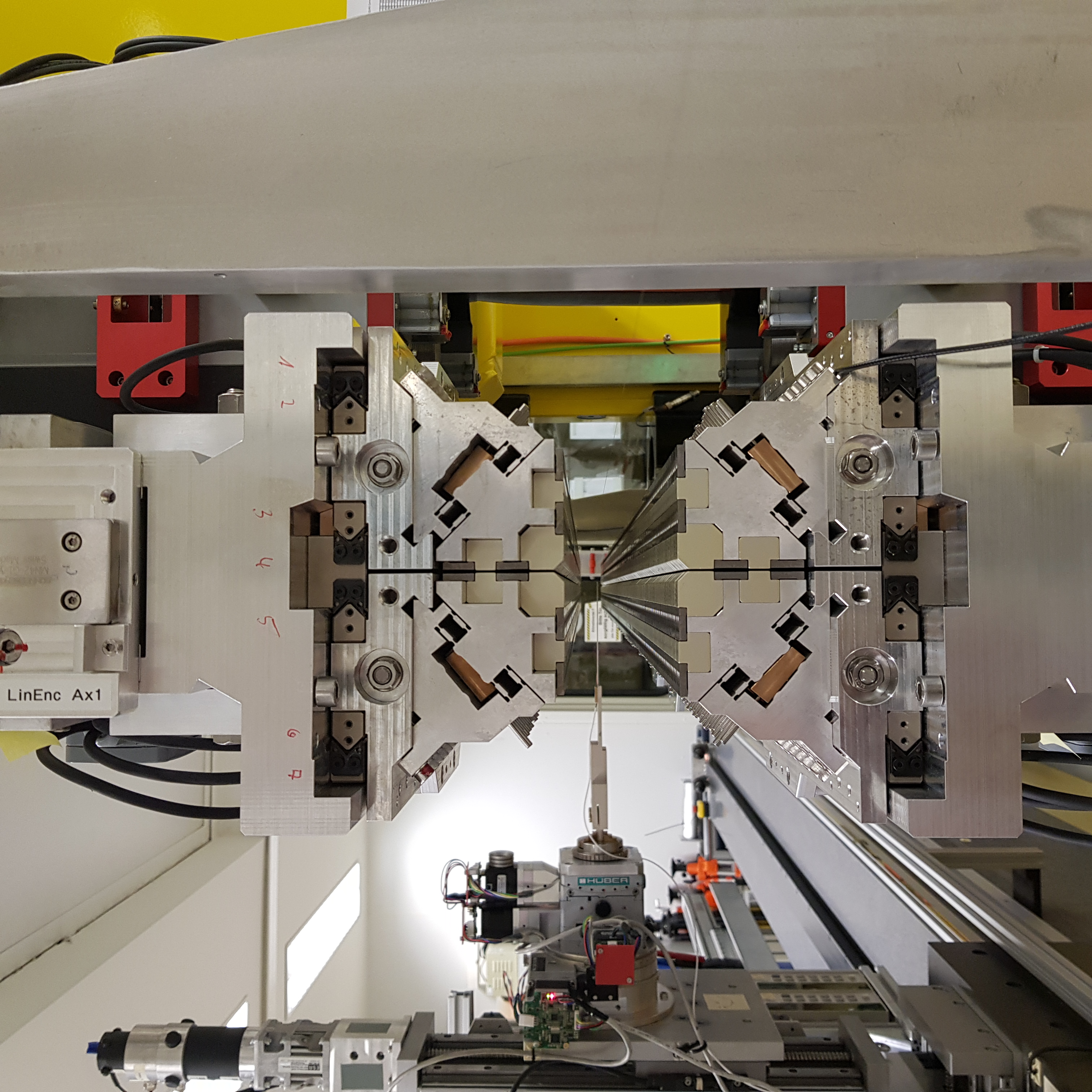
The use of circularly polarized soft X-rays at the FLASH-FEL at DESY is a versatile tool for investigation of dynamic properties in nanomagnetism. For that purpose, a variable polarization undulator of type APPLE III was developed to provide an afterburner downstream of the FLASH2 SASE undulators. It serves to produce circularly polarized light with a wavelength of 1.33 nm to 1.77 nm (890 eV - 700 eV) to investigate the L-edges of Fe, Co, and Ni. This wavelength range together with the future maximum beam energy of 1.35 GeV at FLASH leaves only a small and ambitious parameter window for the undulator if a noteworthy tunability range shall be provided.
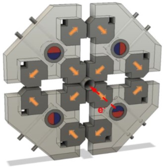
In the APPLE-III configuration, the magnet structure consists of four permanent magnet arrays in Halbach configuration, where the B magnets of the inner arrays around the circular beam pipe are transversely magnetised with their easy axis along the 45° direction. The outer arrays form the force compensation scheme and need to be implemented between both, top and bottom girder and also between rows on each girder.
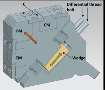
Two types of magnets, commonly named A and B, are used to build the APPLE-III magnetic structure: Type A is magnetised along the short edge, while type B is magnetised along the diagonal of the large plane. In order to improve stability and to simplify the mechanical design, magnets of type A and B are glued together in pairs. The gluing of the magnet pairs for the full-length device is carried out after complete randomization of the magnets to reduce systematic errors. All magnet pairs are then characterized by a Helmholtz coil set-up and by stretched-wire measurements. Based on our experiences with a prototype, the design of the keepers was made more rigid: the new keeper contains two pairs of glued AB- or BA-magnets. One such pair corresponds to half a period and two pairs are mounted in each keeper which then contains one full period. Besides the function magnet (FM) pairs, the keeper also contains the force compensation (CM) magnets. They are similar in size and shape to the function magnets and are also glued together in pairs. The new keeper has a movable wedge and the tuning mechanism with two differential thread bolts per keeper allows for each function magnet pair to be adjusted individually perpendicular to the beam.
Contact: M. Tischer, K. Götze, P. Vagin
Publications and further literature:
M. Tischer, H. Bienert, K. Götze, D. Meissner, P. Neumann, P. N'Gotta, T. Ramm, A. Schöps, P. Talkovski, S. Telawane, P. Vagin. J. Phys.: Conf. Ser. 2380 012017 (2023).
Force Compensation Concept (Apple2): BESSY, SRI2018, AIP Conf. Proc. 2054, 030031 (2019).
Liang X, Calvi M, Kittel C, Sammut N J, and Schmidt T 2019 Proc. FEL'19 541‒544.
Bahrdt J and Grimmer S 2019 Proc. SRI Conference 2018, AIP CP 2054 030031-1‒6.
Bahrdt, J., H. J. Baecker, W. Frentrup, A. Gaupp, M. Scheer, B. Schulz, U. Englisch, and M. Tischer. Proc. EPAC08 2219 (2008).
APPLE III concept: Bahrdt J, Frentrup W, Gaupp A, Kuske B, Meseck A, and Scheer M 2004 Proc. SRI Conference 2003 AIP CP 705 215‒18.