


LVP-XPRESS – Large Volume Press X-ray Probe for Research in Extreme Synthesis and Planetary Studies
PETRA IV Phase-I Beamline | Anticipated start of user operation: 2033
What is LVP-XPRESS?
LVP-XPRESS (PB11) is a next-generation experimental station at PETRA IV designed to study materials under extreme conditions — similar to those found deep inside planets or during advanced industrial processing.
Using intense high-energy X-rays and powerful large-volume presses, researchers can observe how materials behave while being compressed and heated to very high pressures and temperatures. Unlike conventional laboratory experiments, LVP-XPRESS allows scientists to see structural changes inside millimetre-sized samples in real time.
Compared to its predecessor at PETRA III (P61B), LVP-XPRESS will provide:
- Significantly brighter X-ray beams for faster and more precise measurements
- High-speed 3D imaging of materials while under load
- More complete structural information during deformation and synthesis
- Improved insight into stress, texture, and phase transformations
LVP-XPRESS will enable breakthroughs in geoscience, materials research, high-pressure chemistry, and industrial innovation — helping scientists understand how materials form, transform, and perform under extreme environments.
Beamline Concept & Scientific Motivation
LVP-XPRESS will be the dedicated high-energy Large Volume Press beamline at PETRA IV. It builds directly on the scientific success of the P61B LVP station at PETRA III and transforms it into a full undulator-based beamline with order-of-magnitude higher brilliance, full 2D angle-dispersive diffraction, and high-speed tomography capabilities.
For more than three decades, DESY has hosted in situ large-volume high-pressure research, from DORIS (MAX80, MAX200x) to the Aster-15 LVP at P61B (PETRA III). LVP-XPRESS represents the next-generation infrastructure for extreme conditions research at PETRA IV.
The beamline addresses growing demand in:
- Geosciences: Deep Earth and planetary interior processes
- Materials Science: Advanced functional materials and metallurgy
- High-Pressure Chemistry: Reaction pathways and synthesis
- Industrial Research: Processing under extreme P–T conditions
The focus remains on millimetre-scale samples under extreme pressure and temperature, enabling experiments beyond the scope of micro-anvil or DAC facilities.
Key Transformative Improvements
- Order-of-magnitude increase in usable monochromatic flux (40–120 keV range) via cryogenic undulator source.
- Transition from ED-XRD (P61B) to full 2D AD-XRD, enabling complete Debye-Scherrer rings.
- Beam flexibility: from micro-focus (~1 µm²) for DSCT to large beams (up to 3 × 3 mm²) for whole-sample imaging.
- Fast CRL transfocator switching (<1 s) for automated diffraction/imaging mode toggling.
Scientific Capabilities
Diffraction:
- Powder and multi-grain diffraction
- Radial diffraction for stress and texture
- Full azimuthal strain analysis
- Pair Distribution Function (PDF) on melts and glasses
Imaging & Tomography:
- Absorption contrast imaging
- Phase contrast imaging
- Diffraction/Scattering Computed Tomography (DSCT)
- 4D time-resolved tomography (sub-second acquisition)
Beamline Layout
LVP-XPRESS is located in sector 1 of the PETRA IV North Hall (46g). The former damping wigglers are replaced by an RF section and a cryogenic CPMU-18 undulator optimized for high-energy flux.
New optical components include:
- Bent-Laue Double Crystal Monochromator (BL-DCM)
- Dual CRL transfocator systems (pre-focus and focus/defocus)
- Heat-load filters, fast shutters, and precision slit systems
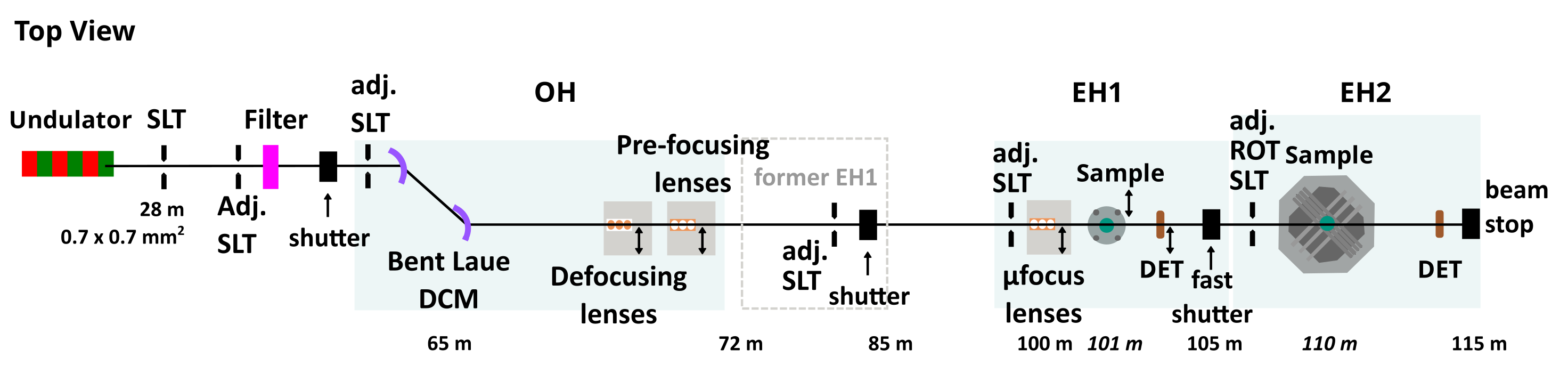
Fig. 1. Schematic layout of LVP-XPRESS at PETRA IV.
Experimental Hutches
EH2 – Aster-15 LVP (~70% beam allocation)
- Routine synthesis and deformation studies
- Radial diffraction & texture analysis
- Ultra-high P–T generation
- Optimized detector distances (1–3 m) for large 2θ coverage
EH2 remains compatible with offline operation when beam is delivered to EH1.
EH1 – Paris-Edinburgh & Portable LVPs (~30% beam allocation)
- PDF measurements on melts and glasses
- Diffraction/Scattering CT (DSCT)
- High-speed 4D tomography
- Compatibility with user-supplied compact presses
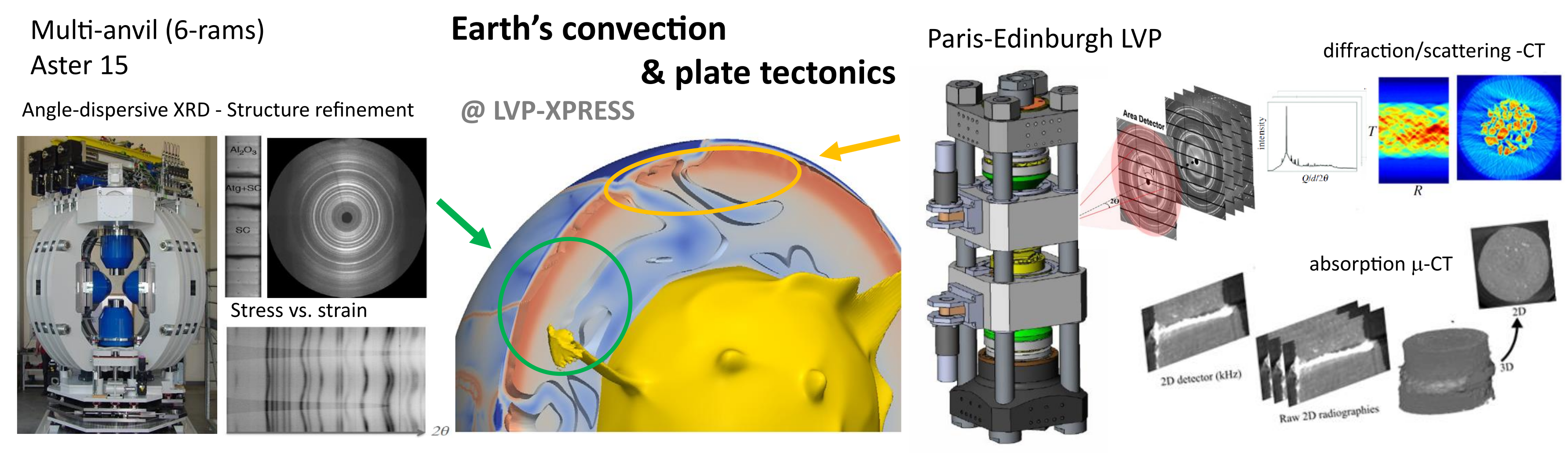
Fig. 2. Representative diffraction and tomography modes in EH2 and EH1.
Detectors
LVP-XPRESS will operate exclusively in angle-dispersive geometry with:
- High-energy photon-counting CdZnTe detectors
- High-frame-rate integrating area detectors
- Zero-noise high-speed cameras for imaging
Compared to P61B, this enables complete diffraction rings, improved strain/texture analysis, higher dynamic range, and millisecond-scale acquisition.
Data & Scientific Computing
PETRA IV operation implies data volumes of several terabytes per day. LVP-XPRESS will provide:
- Automated data reduction pipelines
- Real-time tomographic reconstruction
- Immediate experimental feedback
- Integration with DESY high-performance computing infrastructure
Why LVP-XPRESS Matters for P61B and New Users
- ~10× higher monochromatic flux
- Full 2D AD-XRD instead of ED-XRD
- True diffraction tomography (DSCT)
- Micro-beam mapping down to 1 µm
- High-speed 4D tomography under load
- Expanded strain and texture capabilities
P61B → PB11 Evolution
PB11 LVP-XPRESS represents the natural technological evolution of the P61B LVP station. The table below summarizes the key performance and capability upgrades enabled by PETRA IV.
| Category | P61B (PETRA III) | PB11 LVP-XPRESS (PETRA IV) | Impact for Users |
|---|---|---|---|
| Source | Damping Wigglers | Cryogenic CPMU-18 Undulator | ~10× higher usable monochromatic flux |
| Diffraction Geometry | Energy-Dispersive (ED-XRD) | Full 2D Angle-Dispersive (AD-XRD) | Complete Debye-Scherrer rings, full azimuthal strain & texture analysis |
| Time Resolution | 1 - 100s of seconds | Milliseconds | True time-resolved deformation and reaction studies |
| Beam Size | ~50–100 µm (EDXRD), 2 mm (radiography only) | 1 µm – 3 mm (switchable) for both AD-XRD and Imaging | Micro-mapping (DSCT) to whole-sample imaging in one setup |
| Tomography | No capability | High-speed 4D CT & Diffraction/Scattering CT | Simultaneous structural and spatial information under load |
| Stress & Texture | Partial information | Full 2D ring analysis at 1–3 m detector distance | Quantitative lattice strain and texture evolution |
| Experimental Automation | Manual mode switching | Sub-second CRL transfocator switching | Scripted diffraction/imaging workflows |
| Data Infrastructure | Standard acquisition | Automated pipelines & real-time reconstruction | Immediate experimental feedback |
PB11 is not merely an upgrade in flux — it fundamentally expands the experimental parameter space for large-volume high-pressure research.
Summary
LVP-XPRESS secures DESY’s leadership in large-volume high-pressure research and establishes PETRA IV as one of the few facilities worldwide combining large-volume presses, high-energy AD-XRD, diffraction tomography, and millisecond time resolution within a single integrated platform.