


")
")
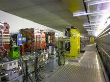
Aerial view of DESY's synchrotron radiation source: the PETRA III storage ring (in blue) with the three experimental halls (in orang) in 2020. (Copyright: © DESY / Reimo Schaaf / Britta Liebaug)

")
")
")
")

")
")


")
")

The basic principle behind the generation of synchrotron radiation was discovered by German physicist Heinrich Hertz (1857-1894). He found that charged particles emit electromagnetic radiation when accelerated. This is because the necessary rearrangement of the electric field around the charge causes a perturbation to radiate outwards at the speed of light: the electromagnetic radiation.
This principle is used in e.g. radio or TV antennae, where charges move up and down periodically in the metal at a frequency specific to the station or channel, thus generating the signal.
The same principle applies for free electrons (or positrons) in an accelerator, although now the source of the radiation is moving. In this case the radiation is seen in the laboratory frame as concentrated in the direction of the electrons’ movement. The effect can be compared to objects being thrown off a fast moving vehicle which would all fly more or less in the same direction. Electrons in an accelerator move almost at the speed of light, i.e. they are “relativistic”. For these electrons the effect is further magnified by relativity:
The beam is concentrated into a forward cone with half angle of typically 0.1 to 1 mrad (1 mrad ~ 0.05 degrees) depending on the electrons' energy which can be measured by the Lorentz factor γ. It relates rest energy and actual energy of the electron through γ = E/E0, where E0=0.511MeV is the electron’s rest energy.
EXAMPLE: For the former DORIS III storage ring at DESY, E amounts to 4500 MeV, giving a factor of γ ~ 9000. Thus the forward collimation to an angular spread of about 1/γ arises from the application of the relativistic Doppler effect in the forward direction as shown in the figure.
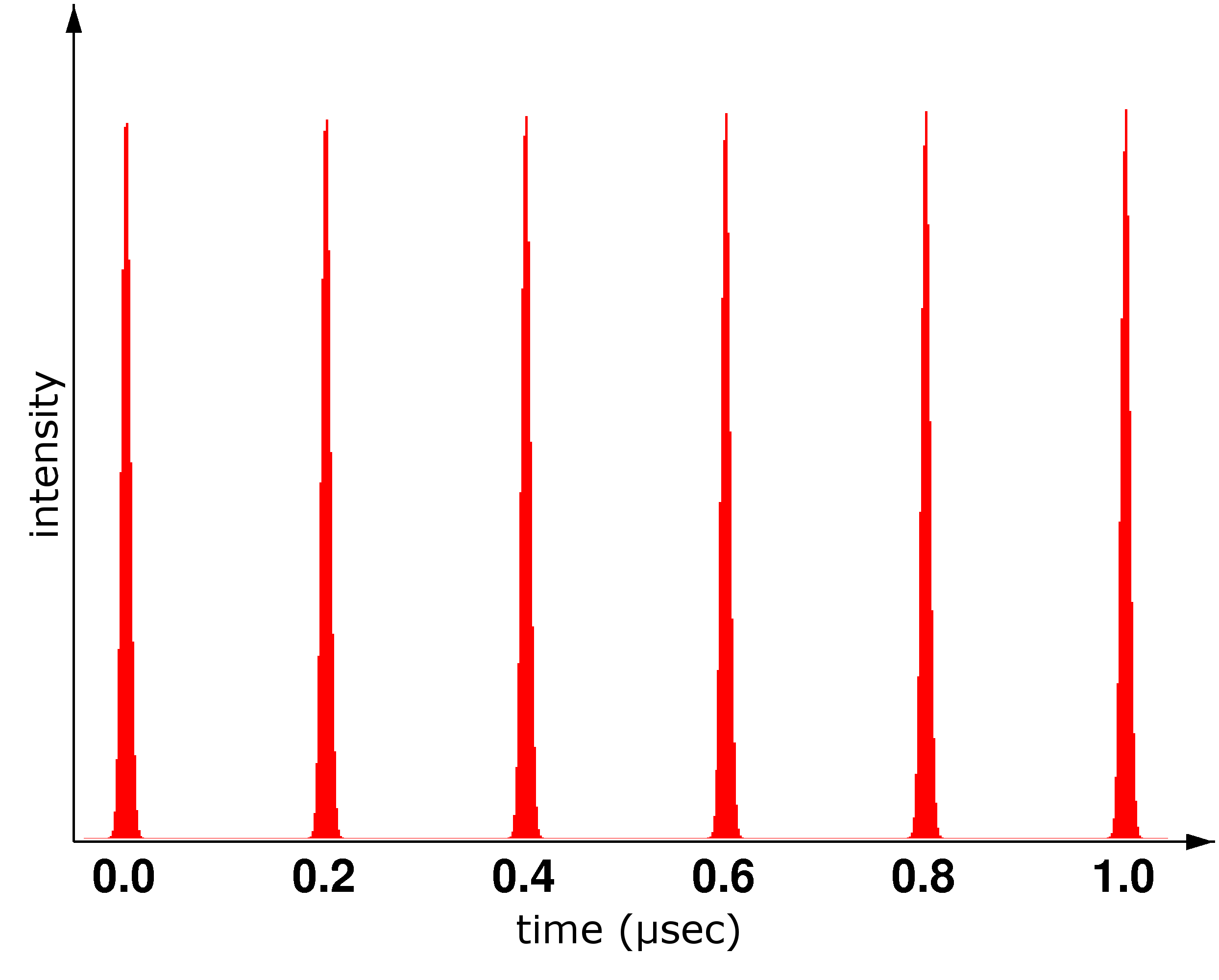
The most common synchrotron radiation sources today are storage rings like the ESRF in Grenoble or PETRA III at DESY, where a “beam” of electrons is stored and kept on a circular path, producing synchrotron radiation used as a light source for experiments. However, the charged particles in PETRA III are not distributed evenly along the accelerator but move in individual packets of ~4.8 x10¹² electrons (so-called bunches). Typcially 960, 480, 60 or 40 bunches of electrons are stored in PETRA III with an beam current of 100 mA in top-up mode. For top-up mode small amounts of current must periodically be injected to maintain a nearly constand beam current (here: 100 mA).
Radiation is produced whenever these bunches are transversely accelerated, e.g. in the bending magnets or special insertion magnet devices, wigglers and undulators. At the experiments, therefore, the light arrives in short pulses. As a typical example of time frames, in PETRA III the pulses last about 100 picoseconds and repeat every 8 ns (960 bunches), 16 ns 128 ns or 192 ns (40 bunches). This pulsed light can be effectively used for specialized research applications needing time resolution.
Polarization:
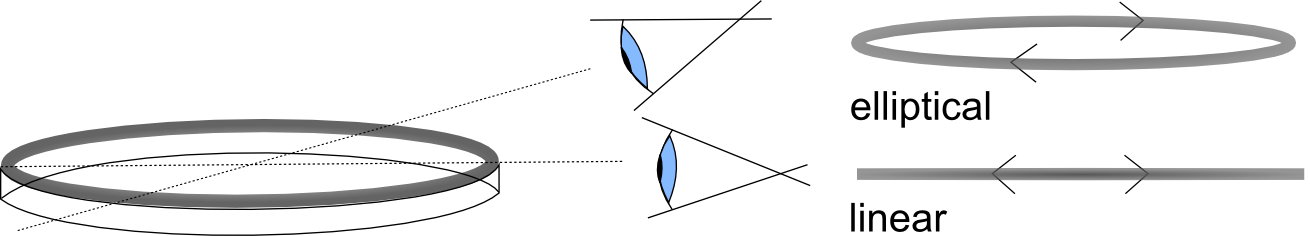
An important property of synchrotron light is its polarization. Looking into the orbit plane of the circulating electrons, the projected movement is an oscillation similar to the simple harmonic motion in an antenna.
This implies that the emitted light is linearly polarized in the orbit plane. Out of plane, the motion is seen as an ellipse and elliptical polarization is observed.
1. As said above, radiation is emitted whenever the relativistically moving electrons are forced to deviate from a straight line motion. This is usually done by applying magnet fields. Bending magnets were the first available sources of synchrotron radiation because they are needed to produce the closed path motion in the storage ring. The radiation has the following characteristics:
- The emission peak is given by λ = c/v, where ν is the “cyclotron frequency”, i.e. the rotational frequency of the motion induced by the magnetic field, again with relativistic effects applied. Taking into account the relativistic mass of the electron and the Doppler shift again gives a wavelength proportional to 1/2γ2.
- The collimation is simply 1/γ as described above.
- The bandwidth is mainly given by the search-light phenomenon. Due to the great collimation, each electron illuminates each detector for only a very short time Δt(like a searchlight), which corresponds to a wide frequency spectrum, i.e. large bandwidth Δλ as stated by the Fourier-theorem. The bandwidth is then given by the equation ΔtΔλ ~ 2πc, leading to Δλ/λ ~ 1.
- Since the magnetic field is determined by the ring’s geometry, the peak is not tunable.
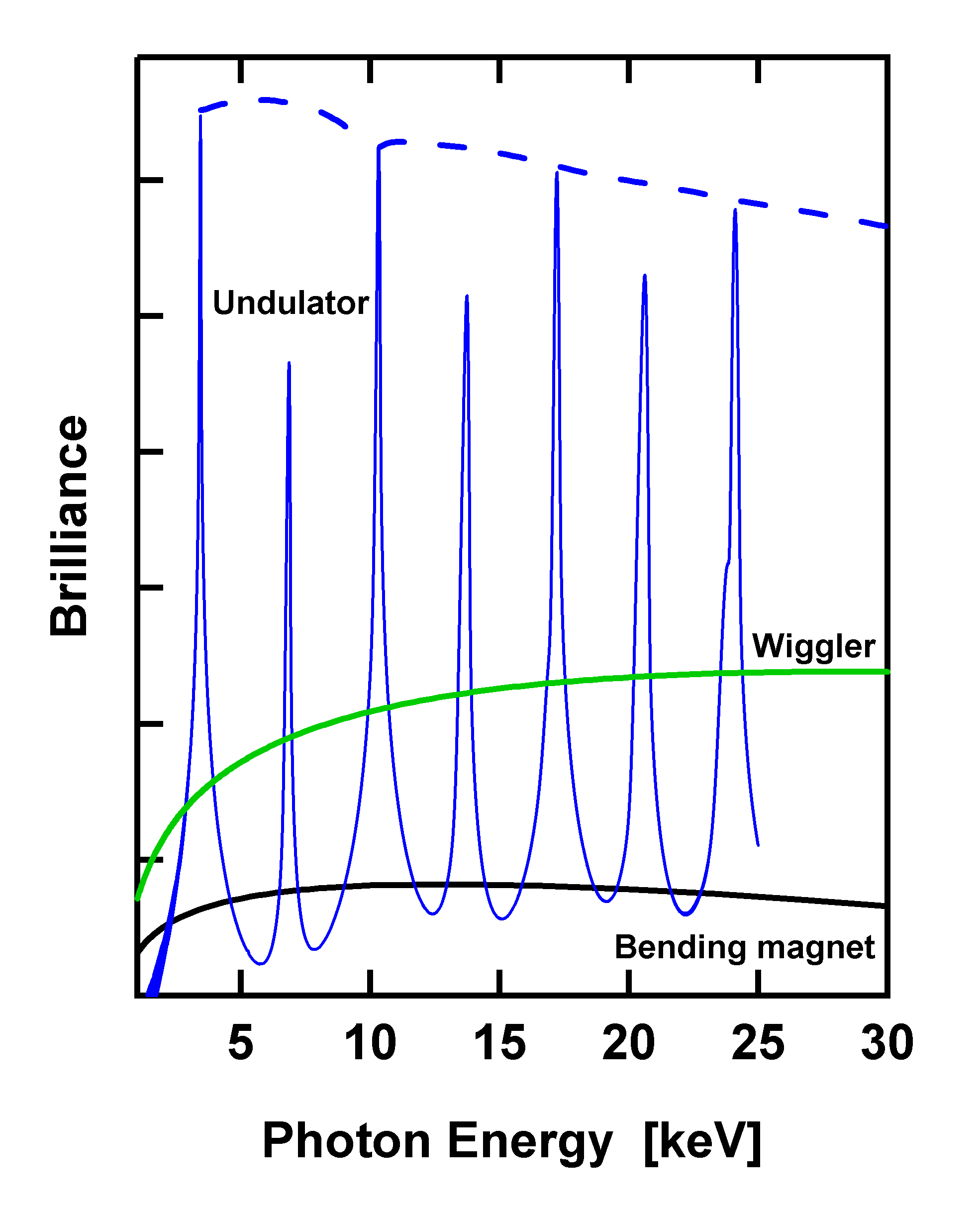
2. Scientists usually never have enough photons for their experiments and like to have a more intense beam. Wigglers are a neat way to increase the intensity of synchrotron radiation by lining up a series of bending magnets which enhances the intensity simply by the number of magnet poles. The generated spectrum is that of a corresponding bending magnet. In order to add up the intensity of the individual emission cones, the dipoles are arranged with alternating polarity such that the electrons are essentially moving straight except for small “wiggles” where the radiation is emitted. The emission cones overlap and the intensity adds up. The advantage of such a wiggler is that it emits intense radiation over a wide spectral range, very much like a bending magnet. At the same time, this is its major disadvantage because most scientific experiments usually only need a very narrow range of wavelengths and therefore most of the wiggler radiation power remains unused leading to unwanted heat production within the optical devices.
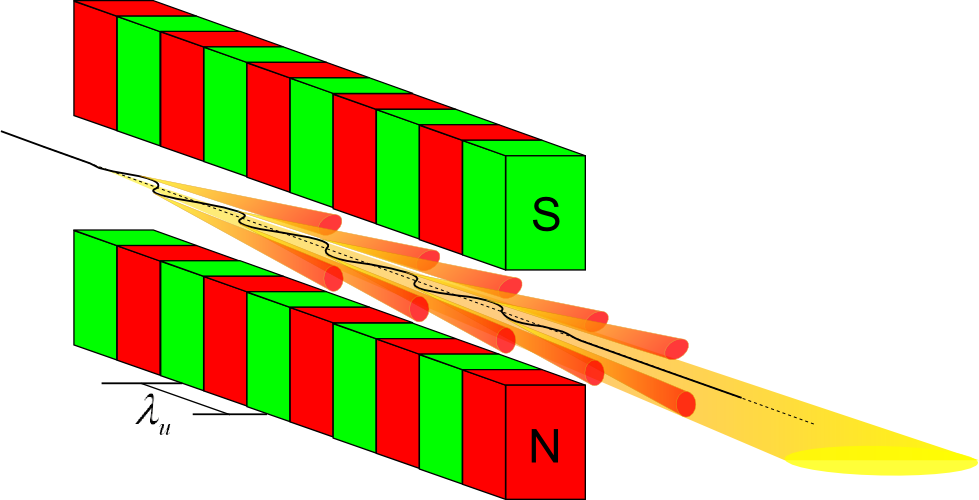
3. Most modern machines preferentially use so-called undulators instead of wigglers. Undulators are the most powerful generators of synchrotron radiation at storage rings. Like wigglers, they consist of periodic arrangements of dipole magnets generating an alternating static magnetic field which deflects the electron beam sinusoidally. As in the example of the antenna, this results in radiation with the wavelength of its periodic motion given by the geometric period length λu of the undulator dipole arrangement, albeit modified by relativistic effects. In the particles’ frame, λu is shrunk by the factor γ due to Lorentz contraction, i.e. the electron ‘sees’ a compressed undulator. For the outside observer, the wavelength is further shrunk by another approximate factor 2γ due to the relativistic Doppler effect. In total, the emitted wavelength observed at the experiment is reduced by a factor ~ γ 2 (~ 106 – 108) with respect to λu. Undulators built to emit X-rays with λ ~ 0.1 nm therefore have a magnet structure with a period length of some cm.
Learn more about undulators and wigglersThe properties of undulator radiation are, simply put:
- The peak emission wavelength is given by the undulator’s physical period length λu shrunk due to relativistic effects.
- Taking into account angular effects as well shows that the wavelength also depends linearly on the magnetic field, meaning the radiation is tunable.
- The special properties of undulator radiation arise from the fact that due to the small amplitude of the oscillations the radiation cones emitted during each oscillation period overlap and interfere.
-
This means the series of N magnets acts similar to a diffraction grating, generating a spectrum of peaks due to constructive and destructive interference of the radiation cones. The natural bandwidth of the first harmonic is
 .
. -
Also the intensity of the peaks is
 , meaning the radiation has far higher intensity than bending magnet or wiggler radiation, although not a continuous spectrum (see on the left).
 -
Since the wavelength shifts when going away from the centre of the beam, the fact that the natural bandwidth can not be exceeded also limits the spread of the cone to an approximate half angle of around
 , meaning the beam is more collimated than that of a wiggler or bending magnet.
Very important properties of synchrotron radiation are also:
Flux and Brightness:
The quality of a light source depends, simply speaking, on getting as much light as possible on the sample per unit area and time. To achieve this two things are important: The total flux F emitted by the source needs to be maximized and the flux must be concentrated or “bright/brilliant”.
The concentration depends on the angular divergence Δθ and the beam size Δy. It can be shown that beam optics can never change the product Δθ·Δy. This leads to the expression 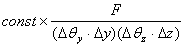 for the “brilliance” of the light source, which is to be maximized.
The output of synchrotrons experienced much advancement over the years which can be explained by two things: In the storage rings used today the beam cross-section is extremely small, and as shown above the radiation is also very well collimated. It can also be shown that  , which greatly amplifies the advances in electron energy, which is proportional to γ.
Coherence:
A simple definition of coherence would be saying that a wave is coherent if it can produce detectable wave-like effects like diffraction and interference.
Time or longitudinal coherence is described by the bandwidth of the radiation. Looking at two wavelengths λ and λ + Δλ the diffraction maxima are still discernible if Δλ/λ > 1.
Since this is usually not true for bending magnet or wiggler radiation additional monochromator devices (which lower Δλ) are needed to achieve time coherence. Undulators need this only in some exotic applications.
Spatial or lateral coherence is described by the spatial extension Δy of the beam.
Simplifying the picture to two emitting points Δy apart gives the condition for coherence as ΔyΩy < 2λ, where Ωy = d/D. This means increased “brightness” has the additional positive effect of increased spatial coherence.
The absolute theoretical limit for improvement of these geometrical characteristics is given by Δθ·Δy ~ 2λ, where modern light sources reach values for λ of about 100-1000Ǻ.
All these properties arise from comparatively simple relativistic calculations.
Further useful information is also available in the "X-RAY DATA BOOKLET" from the Lawrence Berkeley National Laboratory (US).