P61A - OH and EH layout
I. General specifications
Beamline calculations can be viewed here (PDF file)
Full beamline layout incl. P61B (click for larger view)
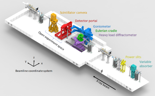
The OH houses a continuous variable thickness absorber (choice between Cu or C) and beam defining power slits.
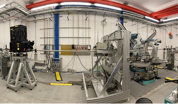
The EH houses a long radius detector goniometer where different detectors can be mounted, an HPGe detector portal, a high-speed scintillator camera and a heavy load diffractometer. A heavy load Eulerian cradle can be mounted on top of the heavy load diffractometer. In most experiments, sample or sample environments are mounted on the heavy load diffractometer or Eulerian cradle. A 3 m long space is available behind the diffractometer for roll-in, roll-off setups, or for sample environments which cannot be mounted on the diffractometer. The detector portal and camera can be moved around the hutch to address each experiment’s needs.


P61A EH
|
Techniques available
|
Energy dispersive X-ray diffraction in Transmission and reflection
High speed radiography
|
|---|---|
|
Photon source
|
10 wigglers
|
|
Max. source flux
|
1012 ph/s/0.1% b.w. (at 50 keV, 100mA, aperture 1 x 1 mm2 at 133 m from source)
|
|
Energy range
|
20 - 200 keV
|
|
Filters
|
Minimum: 300 micron CVD-diamond + 50 micron Cu
Maximum: 900 micron CVD-diamond + 150 micron Cu Variable Cu or C attenuator 0-100mm |
|
Spot size ON SAMPLE
|
min. 0.05 x 0.05* mm2
max. 2.0 x 1.5 mm2
*smaller beam size is possible in special conditions
|
|
Sample type
|
polycrystalline materials
|
II. Positioning Instruments
Heavy Load Diffractometer
Load capacity: 1 ton centered, 600 kg off center
Max distance from mounting platform to beam: 450 mm
Axis names:
|
Axis
|
Travel Range
|
|---|---|
|
hl.x
|
1000 mm
|
|
hl.y
|
1000 mm
|
|
hl.z
|
200 mm
|
|
hl.rx
|
±7o
|
|
hl.ry
|
±7o
|
|
hl.bet
|
-90 to 270o
|
|
hl.alp
|
±5o
|
Eulerian Cradle
Load capacity: 20 kg
Sphere of confusion: <50 µm
Max distance from mounting platform to beam: 200 mm
Axis names:
|
Axis |
Travel range |
|---|---|
|
eu.x |
150 mm |
|
eu.y |
150 mm |
|
eu.z |
50 mm |
|
eu.phi |
± 180° |
|
eu.chi |
± 90° |
Examples of clamps and different samples mounted on the cradle:
Goniometer
The goniometer has two arms (which can be used simultaneously and moved independently) aligned with a vertical scattering plane. Routinely, one of the arms carries an HPGe detector. User supplied detectors can be mounted as well.
|
Load Capacity |
50 kg on lower arm, 20 kg on upper arm |
|---|---|
|
Sphere of confusion |
< 50 µm |
|
Max distance from mounting platform to beam |
320 mm |
|
Minimum angle between arms |
20° |
|
Lower arm movement range |
0-50° |
|
Upper arm movement range |
20-70° |
Detector Portal
The detector portal has two arms carrying an HPGe detector and associated motorized double slits. Both arms can be independently positioned in four degrees of freedom (translation on x and z, rotation around x and z). The angular movement ranges on routine operational conditions are shown below:
|
Vertical tilt range |
3.5-10° |
|---|---|
|
Horizontal tilt range |
6.5-15° |
Movement ranges depend on the relative position between detector portal and sample. The position of one detector arm can limit the movement range on the other arm. Larger and lesser angles are possible when non-routine detector arm and detector portal positions are used.
III. Detectors
HPGe Detectors
The beamline is equipped with three HPGe detectors (Mirion) with associated Xspress3 readout units (Quantum Detectors).
|
Sensor dimensions |
12 mm diameter, 10 mm thickness |
|---|---|
|
FWHM @ 122 keV |
475 eV |
|
Energy range |
0-204 keV |
|
Acquisition # of bins |
4096 (~50 eV bin size) |
|
Optimized max count rate |
100 kcts/s |
|
Saturation count rate |
~ 1000 kcts/s |
Scintillator camera
The camera is comprised of a scintillator mount, 5 or 10 x magnifying optics, and a Phantom v2640 camera sensor. Routinely, 400 µm GaGG+ scintillators are used, although other scintillators are possible.
|
Sensor size |
2048x1952 |
|---|---|
|
Bit depth |
12 bits |
|
Pixel size @ 5x |
2.7 µm |
|
Pixel size @ 10x |
1.35 µm |
|
FOV @ 5x |
5.5 x 5.2 mm2 |
|
FOV @ 10x |
2.7 x 2.6 mm2 |
|
Max frame rate* |
6.6 kHz |
|
Max frame rate* |
25 kHz |
*Higher frame rates are possible if the image size is cropped.
IV. Infrastructure
The experimental hutch is equipped with signal, power and media lines for supporting user experiments. A manually operated bridge crane is available for mounting/unmounting instruments inside the hutch.
Bridge Crane:
2 ton load capacity, max hook height: 3.5 m (door height: 2 m).
Signal:
Patch panel routed to control hutch containing several BNC, SHV and AB ethernet ports.
Power:
Besides standard power plugs, 5 pole CEE connectors are available for 400V and 16A, 32A and 64A.
Media:
- Compressed air, 6.5 Bar. Connector: DN 7,2 Type 26, 6 mm.*
- Cooling water (usage of cooling water requires pre-approval from Petra infrastructure groups, please contact the beamline staff in advance).
- N2, 0.5 Bar. Connector: 10 mm Swagelok quick connector. *
- Inert gas lines (routed to gas bottle cabinet outside the hutch). Connector: 6mm Swagelok fitting. *
- Gas exhaust ports. Connector: KF40
*There are adaptors on site for common hose and tube sizes. If specific communication or signal cables are needed, they can be routed outside of the hutch through the access chicanes.
Connector layout:
V. Control/Data analysis
|
Software type
|
Python-based, spock (Sardana)
|
|---|---|
|
Data output type
|
spectra x position, stress x position, additional parameters such as temp., incident and transmitted beam intensity, etc.
|
|
Data output
|
ascii, HDF 5
|
|
Software(s) for quantitative analysis
|


