


The present design for the planar undulators was developed during the upgrade of PETRA III towards a 3rd generation light source and the planning for the European XFEL project. An extensive common development had been started for these insertion devices since their properties had to comply with the specifications of both projects. It was done in close collaboration with DESY’s central design department and was also adapted for the sFLASH and FLASH 2 undulators
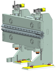
A large girder cross section of 500 by 100mm was chosen to minimize shear deformation. The girders are connected to massive guideways and lead screws integrated in the support columns using spherical supports. In this way the magnetic forces are transmitted, and a rotational degree of freedom is provided. The exact parallel alignment of top and bottom girder can later be adjusted by additional setscrews.
The 5m long undulators and first series of 2m insertion devices (IDs) have four motors, one for each spindle, which are electronically synchronized. The FLASH2 and present 2m IDs have a 2-axis drive with mechanically coupled left/right thread spindles.
The control system is based on commercially available industrial components. It is based on bus terminals on a rail mount using an EtherCAT fieldbus to drive the servo motor controllers and auxiliary hardware. Additional linear encoders are mounted like large callipers between the ends of both girders to measure the exact height of the gap and provide this information as feedback for the motors. The undulator control system has an interface to the accelerator control system via TINE. For the experimental stations, there is an additional interface via ADS and TANGO. For the FLASH IDs, a Modbus-Server on the undulator control system provides an interface to the global FLASH controls via DOOCS.