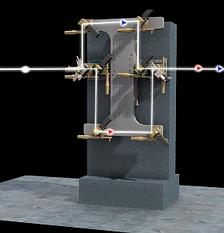
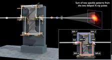
Figure 1: Illustration of the split-and-delay XPCS technique. A single X-ray pulse is split into two equal intensity pulses using the hard X-ray delay line. The pulses propagate collinearly in the sample direction. Inset: Concept of the hard X-ray delay line. BR-1 to BR-6, Bragg reflectors; BS: beam splitter, BM: beam mixer. The paths of the upper and lower branch of the delay line are denoted by blue and red lines, respectively.
Wojciech Roseker1, Hermann Franz1, Anita Ehnes1, Horst Schulte-Schrepping1, Olaf Leupold1, Federico Zontone2, Aymeric Robert3, Gerhard Grübel1
1. Hamburger Synchrotronstrahlungslabor am Deutschen Elektronen Synchrotron (DESY), Notkestrasse 85, D-22603 Hamburg, Germany
2. ESRF, European Synchrotron Radiation Facility, BP 220, 38043 Grenoble CEDEX, France
3. SLAC National Accelerator Laboratory, 2575 Sand Hill Road, Menlo Park, CA 94025, USA
Published as: “Performance of a picosecond X-ray delay line unit at 8.39 keV”, Optics Letters 34, 1768–1770 (2009).
Although X-ray free-electron lasers provide extremely intense and coherent pulses, their time structure can compromise the applicability of experimental techniques such as X-ray pump/X-ray probe or X-ray photon correlation spectroscopy (XPCS). To fully exploit the potential of XFEL light with the aforementioned techniques we have developed a hard X-ray delay line, i.e. a device capable of splitting a single X-ray pulse into two, delaying one of the pulses and recombining both pulses on a common path. The initial tests of the device were carried out with 8.39 keV radiation. Delay times between the two split pulses of up to 2.63 ns have been achieved with a 16.7 ps time resolution.
X-ray free-electron laser sources will produce ultrashort, coherent and very intense pulses creating excellent conditions for investigation of ultrafast phenomena [1,2].
The accessible time windows are however influenced by the intrinsic time structure of the machine. The European XFEL facility in Hamburg, Germany will provide 100 fs short single pulses separated by 200 ns arranged into bunch trains of 3000 pulses arriving with a repetition rate of 10 Hz [1]. Studying dynamics with XPCS [3] or via the X-ray pump/X-ray probe technique on time scales shorter than 200 ns will thus not be feasible at the European XFEL. One way to overcome this limitation is the split-and-delay approach [4]. Fig. 1 illustrates this approach with the XPCS method. The technique is based on splitting each X-ray pulse into two equal pulses, separating them in time and bringing them back on the primary beam path. The speckle pattern obtained from the sample, which is illuminated by both pulses, is summed on the area detector. Dynamics of the sample are studied by analyzing the contrast in the summed speckle patterns as a function of the applied delay times (i.e. time intervals between the two pulses) [5].
The concept of an X-ray delay line is shown in the inset of Fig. 1. The device consists of eight single crystals arranged in 90° vertical-scattering geometry. An incoming X-ray pulse is split by a first crystal (BS) into two pulses that propagate along two unequal rectangular paths. One part of the pulse is guided by Bragg crystal reflectors BR-1, BR-2, and BR-3 (blue line). The path of the second pulse is defined by the crystals BR-4, BR-5, and BR-6 (red line). Both beams are recombined with the help of the beam mixer (BM). The beam is reflected inside the delay line by using perfect Si(511) crystals oriented in symmetric Bragg geometry (called Bragg crystals) [6]. Beam splitting and mixing is accomplished by wedge-shaped Si(511) perfect crystals oriented in Laue geometry (called Laue crystals). The time interval τc between the two split pulses is defined by ΔL/c, where c and ΔL are the speed of light and the path length difference between the upper and lower branch of the delay line, respectively. A change of the delay time τc is achieved by simultaneous vertical movements of the crystals BR-1, BR-2, BR-5, BR-6 in the direction perpendicular to the incident beam. The setup works in a fixed 90° scattering geometry to optimize the delay time adjustment. In this case a single translation is sufficient to change ΔL. The present design limits the operation of the delay line to a single energy. A 3D model of the delay line is shown in Fig. 1.
Preliminary performance tests of the delay line were carried out at the beamlines C and W1 of the DORIS III storage ring at HASYLAB. The results, which we present here, were obtained at beamline ID10C at ESRF. The performance of the delay line optics has been verified with 8.39 keV X-rays. The throughput of the delay line obtained with a Si(333) pre-monochromator and a photon beam divergence of 17 μrad was measured by comparing incident and exit intensities, yielding a value of 0.6 %.
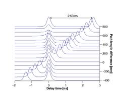
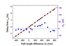
Fig. 2(a) shows a graph of pulse patterns recorded during four-bunch mode operation of the ESRF storage ring. The time interval between detected photons and the synchrotron bunch clock signal was measured in a stroboscopic manner [7] with different path length differences ΔL of the delay line. A maximum delay time of 2.626 ± 0.003 ns was achieved in the experiment. Fig. 2(b) shows a plot of the measured delay time τm as a function of the path length difference ΔL. The solid line is a least-squares fit to the data, which yields a slope of 3.35 ± 0.01 x 10⁻³ ns/mm. In addition the delay time error Δts = τm − ΔL/c was extracted for every data point. The results are also shown in Fig. 2(b). The mean error is 16.7 ps. Since the uncertainty of setting ΔL is only 0.5 μm (i.e. 7 fs), the main contribution to the obtained error is due to the limited time resolution of the detection system. The results have shown that the X-ray delay line is operational for first experiments with XFEL radiation. Upgrades are under further development to achieve higher throughput and broader energy tunability.
| References | ||||||||||||||
|
| Contact Information |
|
Wojciech Roseker |
| Further Information |


