


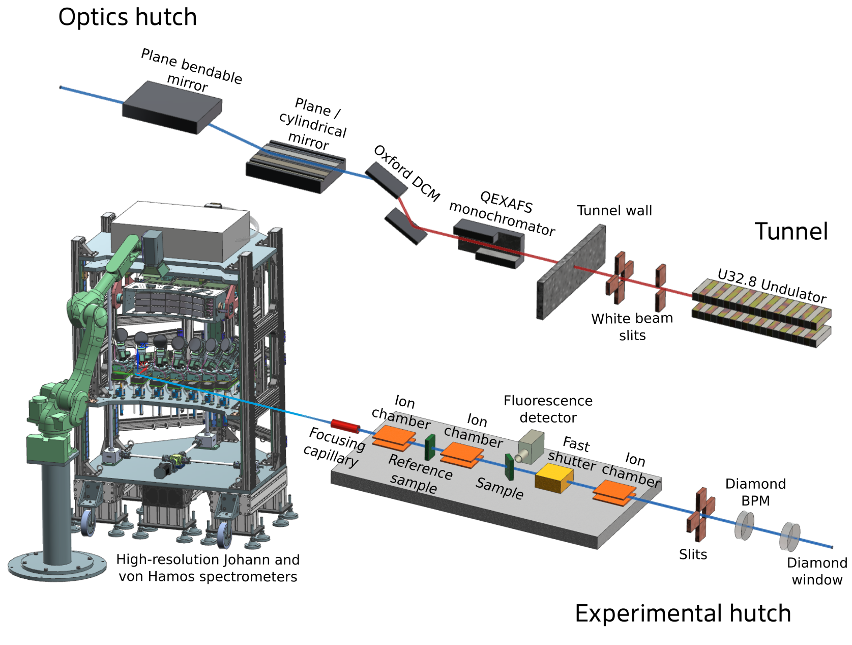
Sketch of the beamline.
The beamline has four different parts:
(1) The period of the undulator was determined by the requested large overlap of the first and third harmonic in order to avoid changes in the harmonic or an intensity variation of more than a factor of 5 over the range of an EXAFS-scan.
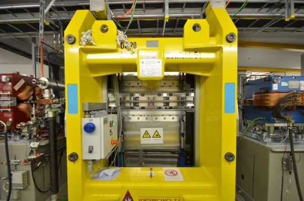
P64 Undulator with open gap in the tunnel. The magnetic structures are clearly visible above and below the rather flat vacuum chamber.
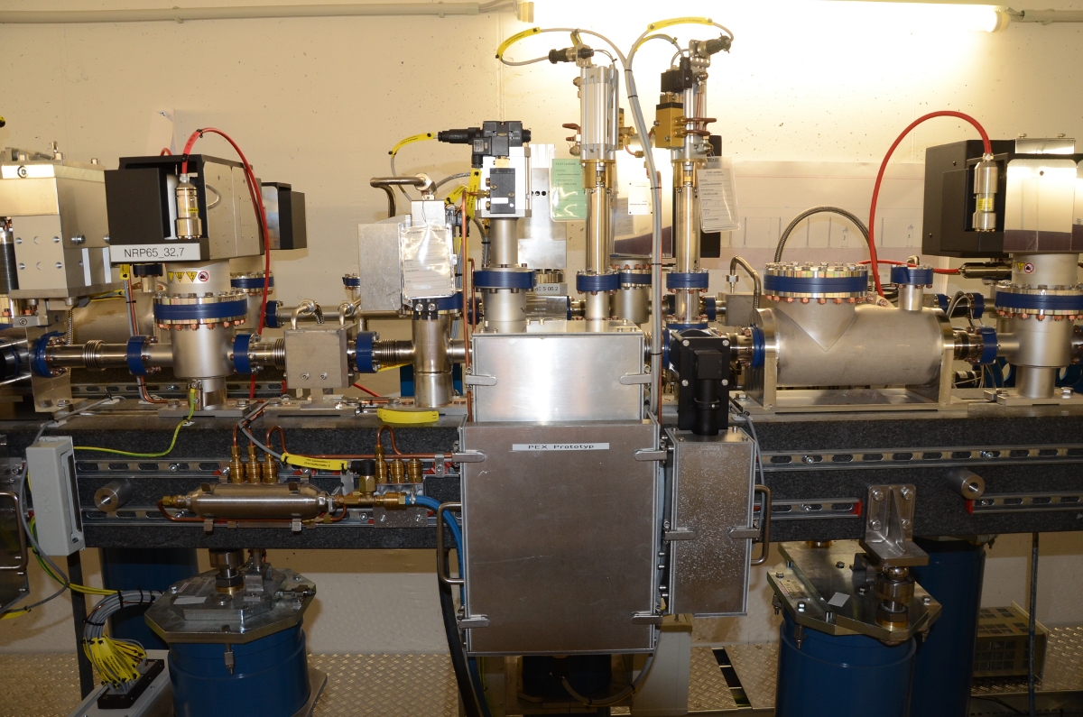
(2) The filter unit of P64 has four different filters: glassy carbon with thicknesses of 0.4, 0.9mm, 1mm, and twice 4mm in three different units.
The slit-system consists of three different pairs of slits: 2 vertical and 1 horizontal pairs. The first vertical pair has a minimum opening of 1mm, the other two pairs can be completely closed.
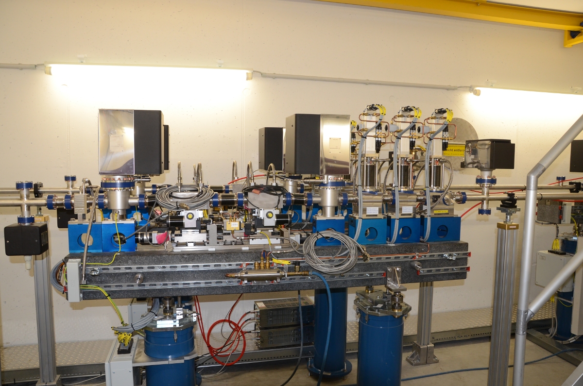
The first girder with beam diagnosis tools.
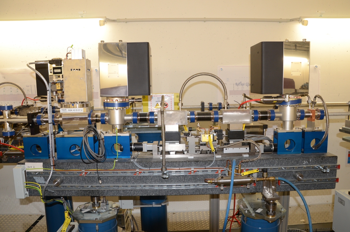
The white-beam slit system and the fast valve.
The filter-unit of P65, the one for P64 is hidden behind it.
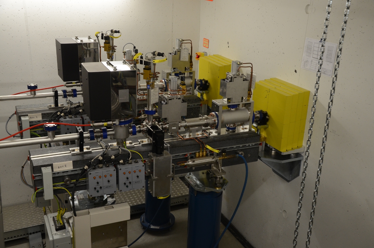
The safety shutters for P64 (background) and P65 (foreground) and additional shielding.
(3) The optics hutch is the first enclosure in the experimental hall. In the case of P64, two different monochromators are installed for separate purposes: The first one is a channel-cut monochromator for fast energy scans within 50ms, and the second one is optimized for conventional energy scans in the minute time-scale with a fixed exit. Two mirrors reduce higher harmonic radiation, and they can be used to focus the beam.
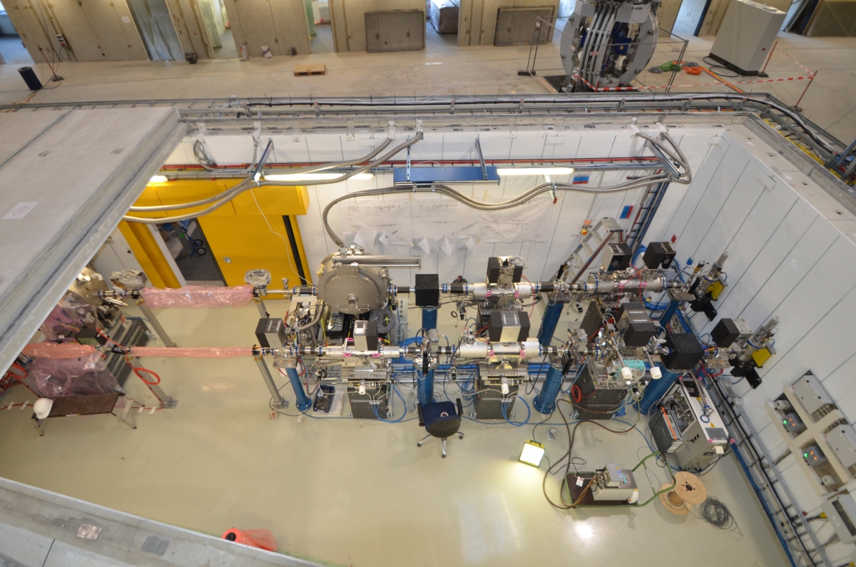
View into the P64/P65 Optics hutch with P65 in the foreground and P64 in the background. The fixed-exit high-heatload monochromator is visible in the middle of the picture. The QEXAFS-monochromator stands on the left side of the picture, and it is partly hidden by the last remaining roof slab.
(4) The experimental hutch is the place where users install the sample and collect data. The sample can be a simple metal foil, and the data are collected in transmission mode with two ion-chambers, or it can be a complex system in a specialized sample-environment like a furnace with different gas-inlets, a mass-spectrometer for measurements of reaction-output, and a fluorescence detector in order to measure low-concentration samples.
")
")
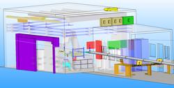
3D Sketch of the experimental and control hutches