1. General
The FLASH is a light source directly coupled to a superconducting linear accelerator operated at 2.2 Kelvin. The whole vacuum system from the FEL to the experiment will be operated without windows. Special requirements on the vacuum system of the beam-line and of the user experiments have to be fullfilled. Hydrocarbons and dust are expected to degrade the performance of the FEL beamline optics and the quality of the photon beam and must therefore be kept on a minimum level. FS will supply an inter-face between the beamline and the experiment to keep the right vacuum conditions in the beamline. To make sure that the experimental end station fits to the requirements of the interface contact FS already in an early stage of a planed project. See also the FS-BT Vacuum Guidelines for Beamlines and Experiments.
2. Oil free UHV and Vacuum Pumps
In order to protect optical elements in the beamline from degradation, the sum of the par-tial pressures of gases having a mass above 45 amu must be below 10-3 of the total pres-sure. FS will provide a residual gas analyser (RGA) in the interface chamber which will allow to monitor the partial pressures. Any one or a combination of the fol-lowing primary pumps may be used: Ion pumps, titan sublimation pumps, and oil-free turbo pumps. Diffusion pumps are not permitted due to their inherent risks of oil con-tamination. Only oil-free mechanical pumps may be used as roughing pumps. Under ex-treme circumstances where no alternatives exist, exceptions to these rules may be given by FS-BT. Efficient differential pumping stages must be installed between those pumps and the last valve of the beamline.
3. Dust Particles
Dust particles on optical surfaces are expected to reduce their performance (radiation damage, scattering) and should be kept on the lowest possible level. Before installation of vacuum components dust should be removed by an appropriate cleaning procedure. In the case that this is not feasible, a pump and purge procedure with dry, particle free nitrogen has to be applied until the numbers of particles in the gas flow is according to the class 100 clean room specification (Clean room classification according to US Fed. Standard 209E). FS provides the tools for this procedure in the experimental hall.
Roughing pumps must be separated from the primary pumps by pneumatic valves which are controlled by the vacuum interlock system of the pumping unit. In the case of a pres-sure or power failure the valves must close automatically.
4. Vacuum Interlock Requirements and Venting Procedure
The beamline vacuum is protected from accidental venting by the vacuum interlock. FS-FL will check the function of the interlock before experiments can start operation. In order to keep dust particles off from sensitive beamline parts a spe-cial venting procedure is necessary. Venting must always be performed with particle free dry nitrogen gas supplied by FS-FL. The venting gas flow is directed in such a way that dust particles move always downstream away from the last beamline-valve towards the experiment. Venting through turbo pumps is not permitted.
5. Experimental Interface

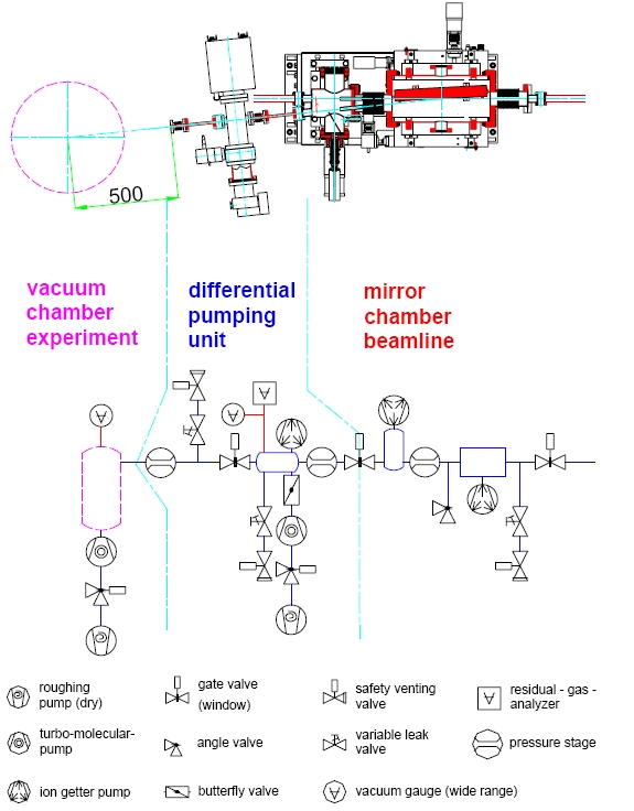
FS-BT will provide at the end of all beamlines a vacuum interface for the user sta-tions. A general layout is shown on the left. The interface includes a permanent differen-tial pumping unit, pressure control units, a residual gas analyser, beamline valves with window, and a remote controlled venting unit. The interface is one of the major safe-guards against the contamination of beamline components by hydrocarbons and dust par-ticles. The residual gas spectra must meet described criteria (see section 2) before an end station can be brought into operation. The differential pumping unit has been designed to cover a pressure gradient range between beamline and the experiment of 3-5 orders of magnitude. The table summarizes upper pressure limits in the experimental end stations for typical gases:
|
Gas |
tolerable pressure |
|---|---|
|
Nitrogen |
10-4 |
|
Argon |
10-4 |
|
Helium |
10-6 |
|
Methane |
10-5 |
In order to protect the beamline in the event of an accidental venting, the vacuum pres-sure of the experimental end station has to be monitored. Therefore, the users have to provide potential free output signals of crucial components like turbo pumps, pneumatic valves, gas inlet pressure and vacuum gauges. The information about the status of these components will be used as input signals for the vacuum interlock system to control the beamline valves.
| PDF Documents |
 Vacuum Guidelines (133KB) Vacuum Guidelines (133KB)
Vacuum Guidelines for Experiments at the FLASH
 Anschlussbelegungen (1.3 MB) Anschlussbelegungen (1.3 MB)
Anschluss der Experimente an das FLASH Vakuuminterlock
|


