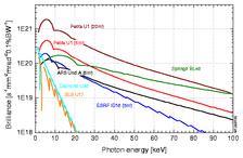
Figure 2: Comparison of the brilliance of two typical PETRA III undulators with those of other third generation sources. The calculations assume ideal undulators, e.g. the brilliances in the higher energy region will generally be marginally smaller.
A minimum aperture of 7 mm and state of the art vacuum pipe design would allow magnetic gaps of the insertion devices down to 9-10 mm without the need of in-vacuum devices. The gaps of in-vacuum devices could probably even be lower than 7 mm as it has been demonstrated successfully e.g. at Spring8, ESRF and SLS. In Tab. 3 typical values for possible b-functions and photon source sizes at the envisaged insertion device positions are listed and compared with the corresponding values of other 3rd generation high energy sources. The PETRA III values are preliminary since the optimization procedure is still under way.
|
bx |
by |
Sx |
Sy |
Sx¢ |
Sy¢ |
ID-length |
|
|---|---|---|---|---|---|---|---|
|
low-b |
1.2 |
4 |
34.5 |
7.3 |
29 |
5.2 |
5 |
|
high-b |
20 |
2.38 |
141 |
4.2 |
8.6 |
5.2 |
5 |
|
20 m-ID |
16 |
10 |
126 |
10.7 |
8.2 |
2.7 |
20 |
|
DW-drift |
16 |
16 |
126 |
12.7 |
10.5 |
4.4 |
5 |
|
ESRF low-b |
0.5 |
2.73 |
60 |
8.4 |
89.3 |
6 |
5 |
|
ESRF high-b |
35.2 |
2.52 |
403 |
8.2 |
11.8 |
6 |
5 |
|
Spring-8 |
24.6 |
3.9 |
384 |
7.1 |
16.5 |
6.6 |
4.5 |
|
APS |
15.9 |
5.3 |
217 |
12.6 |
15.3 |
5.7 |
4 |
The β values for the PETRA III insertion device positions labelled with 'DW-drift' are fixed. For this position is αx=-0.7 and αy=0.7. The a values of all other PETRA III insertion device positions are zero which holds also for the dispersion in the straight ID sections. In Fig. 2 the brilliance of typical PETRA III undulators is compared to other modern third generation synchrotron radiation sources. The parameters used for the calculations of this plots are given in the appendix.
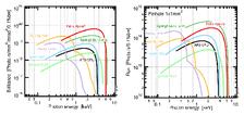
In some cases of existing radiation sources (APS, ESRF) the maximum possible length for an insertion device was assumed even if it does not exist with this length at present. It was shown e.g. by the ESRF insertion device group, that the deviation of a carefully shimmed undulator from an ideal one is about 30 % at the 15th harmonics. This error will increase at higher energies/harmonics. These findings should give an indication for the reliabilities of the calculated values at higher energies ( > 50 keV) in Fig. 2. The brilliance of several PETRA III undulators for different length and electron optics is compared in Fig. 3a. The parameters used for these calculations are given in the appendix. Some of the β-functions used for these calculations are not exactly those given in Tab. 3 which may lead to slightly different results.
Especially the materials science community is interested in photon energies close to 100 keV and more. This is the regime where mainly wigglers have to be used. In Fig. 3b the flux of a number of insertion devices through a 1×1 mm2 pinhole in 35 m distance from the source is compared as function of photon energy. The choice of a 1×1 mm2 pinhole is rather arbitrary and especially the insertion devices with a larger K-value (e.g. all MPW devices) will provide a significant higher total flux through larger apertures.
A number of users on different workshops were interested to learn more about the radiation properties of the damping wigglers at PETRA III. This information is shown in Fig. 4. Obviously these devices provide a rather large beam with significant flux at higher photon energies. If similar properties are of general user interest, it is certainly possible to find more specific solutions to fulfill user demands in the high energy photon regime.
High energy storage rings are very well suited to provide circular polarized soft X-ray undulator radiation which is only obtained at an high degree of polarization in the fundamental line of a helical undulator. A comparison of a proposed PETRA III device with other existing devices is shown in Fig. 5.


