(1)
The basic principle of the free electron laser can be described within the standard picture for the generation of synchrotron radiation: while travelling with relativistic velocity ( ,
, 
 102 - 105) through the undulator, the electrons are accelerated in the direction transverse to their propagation due to the Lorentz force introduced by the magnetic field. They propagate along a sinusoidal path and emit SR in a narrow cone in the forward direction.
The typical opening angle of the wavelength integrated radiation is

where me is the electron mass (511keV/c2) and Ee the electron energy. In the undulator, the deflection of the electrons from the forward direction is comparable to the opening angle of the synchrotron radiation cone. Thus the radiation generated by the electrons while travelling along the individual magnetic periods overlaps. This interference effect is reflected in the formula for the wavelength λph of the first harmonic of the spontaneous, on-axis undulator emission

(2)
where λu is the length of the magnetic period of the undulator and Krms is the "averaged" undulator parameter1

(3)
which gives the ratio between the average deflection angle of the electrons and the typical opening cone of the synchrotron radiation. Bu is the rms magnetic field of the undulator and e the electron charge.
The interference condition basically means that, while travelling along one period of the undulator, the electrons slip by one radiation wavelength with respect to the (faster) electromagnetic field. This is one of the prerequisites for the SASE process of the FEL. To obtain an exponential amplification of the spontaneous emission present in any undulator, some additional criteria have to be met: One has to guarantee a good electron beam quality and a sufficient overlap between radiation pulse and electron bunch along the undulator. To achieve that, one needs a low emittance, low energy spread electron beam with an extremely high charge density in conjunction with a very precise magnetic field and accurate beam steering through a long undulator.
Oscillating through the undulator, the electron bunch then interacts with its own electromagnetic field created via spontaneous emission. Depending on the relative phase between radiation and electron oscillation, electrons experience either a deceleration or acceleration: Electrons that are in phase with the electromagnetic wave are retarded while the ones with opposite phase gain energy. Through this interaction a longitudinal fine structure, the so called micro-bunching, is established which amplifies the electromagnetic field (Fig. 1).
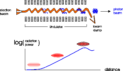
Figure 1: Sketch of the self-amplification of spontaneous emission (SASE) in an undulator resulting from the interaction of the electrons with the synchrotron radiation they emit. In the lower part of the figure the longitudinal density modulation (micro-bunching) of the electron bunch is shown together with the resulting exponential growth of the radiation power along the undulator. Note that in reality the number of micro-bunches is much larger (≥ 105 for the XFELs).
The longitudinal distribution of electrons in the bunch is "cut" into equidistant slices with a separation corresponding to the wavelength λph of the emitted radiation which causes the modulation. More and more electrons begin to radiate in phase, which results in an increasingly coherent superposition of the radiation emitted from the micro-bunched electrons. The more intense the electromagnetic field gets, the more pronounced the longitudinal density modulation of the electron bunch and vice versa.
In the beginning - without micro-bunching - all the Ne electrons in a bunch (Ne ≥ 109) can be treated as individually radiating charges with the power of the spontaneous emission  . With complete micro-bunching, all electrons radiate almost in phase. This leads to a radiation power
  and thus an amplification of many orders of magnitude with respect to the spontaneous emission of the undulator.
Due to the progressing micro-bunching, the radiation power P(z) of such a SASE FEL grows exponentially with the distance z along the undulator [1,11,12]:

(4)
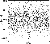
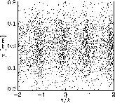
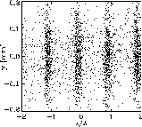
where Lg is the field gain length, Pin the "effective" input power, and A the input coupling factor. A is equal to 1/9 in one-dimensional FEL theory with an ideal electron beam. For the estimation of the effective input power of the shot noise Pin one can use the spontaneous radiation power on the first gain length inside a coherence angle and within the FEL bandwidth. The exponential growth takes place until the electron beam is completely bunched (see Fig. 2) after which it is overmodulated resulting in saturation.
|
|
|
|
Figure 2: Example of the development of micro-bunching of the XFEL electron beam along the undulator. The electron density is represented by the density of the dots (Left: at the undulator entrance, Middle: in the middle of the exponential growth regime, Right: at the undulator exit, i.e. for saturation). Note that only an enlarged section of the bunch is shown. In reality the number of slices (micro-bunches) is much larger. |
||
The main properties of the FEL radiation can be simply estimated in terms of the FEL parameter ρ [10]: the field gain length is  , the FEL amplifier bandwidth Δω/ω and saturation efficiency (ratio of the output radiation power to the electron beam power) are about ρ. This parameter depends on the parameters of electron beam and undulator and is always much smaller than unity (for the TESLA XFELs ρ ranges between 10-3 and 10-4).
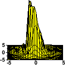
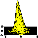
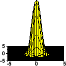
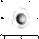
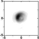
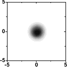
The radiation from an X-ray FEL has a narrow bandwidth, it is fully polarized and transversely coherent. The transverse coherence is also reflected in the development of the transverse intensity distribution along the undulator (Fig. 3) which in the end is nearly Fourier transform limited[1,13].
On the other hand, compared to conventional optical lasers the longitudinal coherence of an X-ray SASE FEL is rather poor which is a consequence of the start-up from shot noise (see Fig. 4). The coherence time is defined by the inverse spectral width Δω and is for XFELs typically much smaller than the electron pulse duration. To improve the longitudinal coherence length, at best up to the full radiation pulse length, a so called "two-stage SASE FEL" is proposed (see [14] and Chap. 4.2.2), where the final output radiation bandwidth is close to the limit given by the finite duration of the pulse.
|
|
|
|
|
|
|
Figure 3: Distribution of the radiation intensity across one slice of the pulse close to the undulator entrance (left), half way through the undulator (middle) and close to saturation (right). The upper figures display the intensity vs. the transverse coordinates, in the lower figures the corresponding polar distribution is shown in units normalized to the radial pulse width σR. |
||

|

|
|
Figure 4: Example of the buildup of coherence along the undulator. The left figure shows the radiation intensity profile half way through the undulator, the figure to the right close to saturation. Please note that for a better visualization of the effect the figures were obtained from a simulation that was made at longer wavelengths and for a coherence length Lc which is 10% of the electron bunch length Lb, whereas for XFELs the typical ratio is |
|
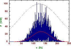
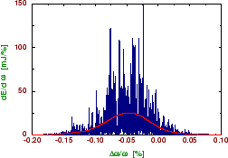
Examples of temporal and spectral structure of the radiation pulse from an X-ray FEL are presented in Fig. 5. The radiation pulse consists of a large number of independent wavepackets which give rise to "spikes". Within one wavepacket, the radiation is transversely and longitudinally coherent. The chaotic nature of the output radiation is a consequence of the start-up from shot noise: since the electron bunch consists of discrete charges randomly emitted from a cathode, the charge density exhibits fluctuations which are random in time and space. As a result, the radiation produced by such a beam has random amplitudes and phases in time and space. These kinds of radiation fields can be described in terms of statistical optics with, e.g., the following parameters: time and spectral correlation functions, transverse correlation functions, probability density distributions of the instantaneous radiation intensity, of its integrals (finite-time and space) and of the energy after a monochromator, coherence time, interval of spectral coherence, coherence area and coherence volume [1].
|
|
|
Figure 5: Typical temporal (left) and spectral (right) structure of the radiation pulse from a SASE XFEL at a wavelength of 1Å. The red lines correspond to averaged values. The dashed line represents the axial density profile of the electron bunch. Note that the growth rate in the electron bunch tail is reduced due to the reduced current. Therefore, the radiation pulse length of 100fs (FWHM) is about a factor of two shorter than the electron bunch. |
|
Using a planar undulator, a SASE FEL also naturally generates higher harmonics, since the micro-bunching of the electrons at the fundamental wavelength of the undulator can also drive substantial bunching at the higher harmonics2. Simulations yield a significant power output of a high-gain SASE FEL which for the third harmonic amounts to several per thousand up to one percent of the first harmonic output power [15,16]. Whereas this nonlinear generation of higher harmonics might be quite relevant when extending the FEL operation range to even shorter wavelengths, all quantitative examples in the scientific case and the following chapters are based on the first harmonic of the XFELs.
1 Please note that for a planar undulator and a sinusoidal magnetic field, the commonly used undulator parameter K is related to Krms by  and equation (3) can be used for K instead of Krms if Bu is replaced by the peak magnetic field B0.
2 This generation of higher harmonics should not be confused with the so called high gain harmonic generation (HGHG) for FELs. Whereas the mechanism is identical, the HGHG consists of an undulator setup creating a micro-bunching at the first harmonic and a second undulator optimized for a higher harmonic which uses the density-modulated bunch to drive the modulation at this higher harmonic.


 .
.