


I. Routine ED-XRD in the LVP
Gauge volume control
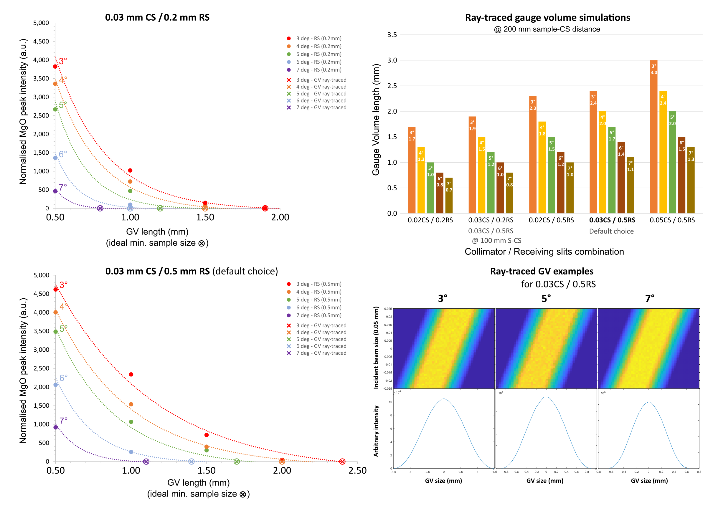
In situ ED-XRD in the Aster-15 LVP at P61B is carried out using 1 or 2 Ge-detectors. The position, i.e. diffraction angle, of the detector can be calibrated before the experiment at angles between 3 and 9 deg. Using the collimator-slit system, this technique offers high spatial resolution and defines a gauge volume from where the diffracted X-rays originate. Normally, this gauge volume should be entirely inside the sample volume. However, depending on the diffraction angle (detector position), diffracted X-rays from the sleeve around the sample cannot be avoided in the detector(s). Measurements were carried out on samples with different diameters (0.5 mm - 2.0 mm) in MgO, and the normalised intensities of the (200) MgO peak in the diffraction patterns were analysed. With increasing sample diameter, this MgO peak from the sleeve around the sample decreased until it was no longer detectable. Ray-tracing simulations of the gauge volume confirmed these observations. The results are shown below:
Pressure calibrations
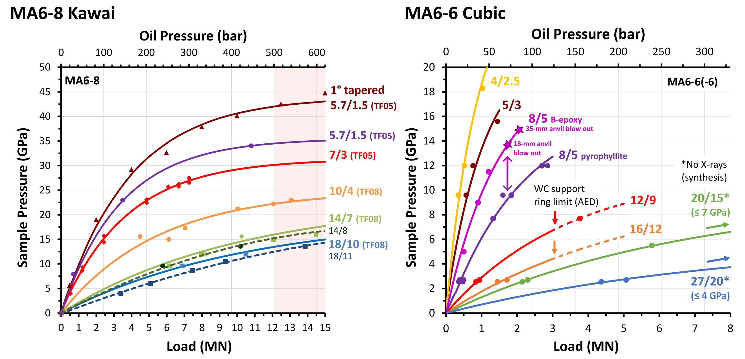
Many different assemlies were calibrated in the LVP. Compression geometries include mainly the MA6-8 Kawai and the MA6-6 cubic configurations. The approximate pressure calibrations for these assemblies are shown below. Note that for deformation experiments (anisotropic compression), it is not possible to go to the pressure 'limit' for the assembly, because the load on the opposite pair of anvils for the advancing rams (1 & 2) increases furthermore. One must consider the upper limit on the press load for these anvils.
Updated: 18.07.2024
II. Ultrasonic Interferometry
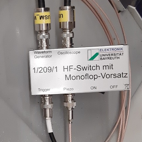
In situ wavespeed measurements in the LVP at HPHT conditions are possible using the Ultrasonic Interferometry system at P61B.
This system comprises:
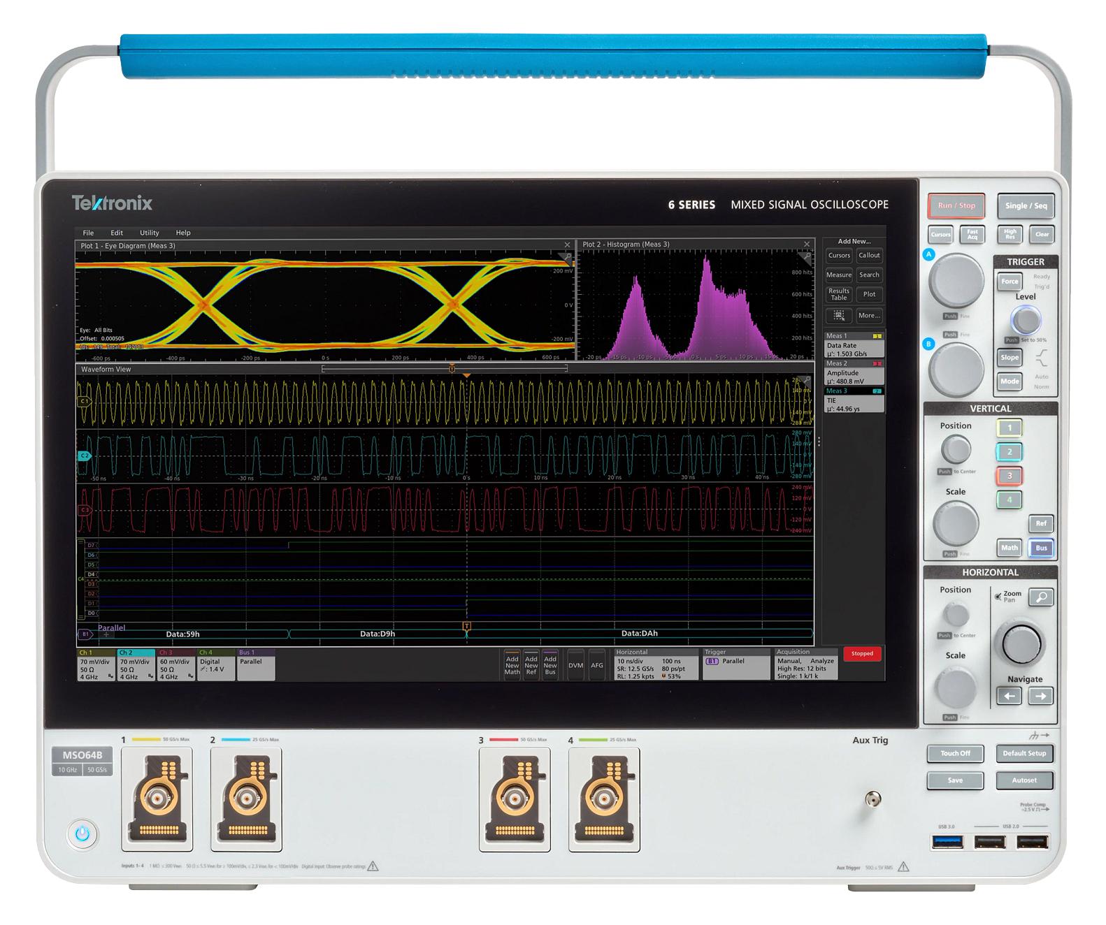
- Oscilloscope: Tektronix MSO 6 series
- 4 Channels
- Sampling rate up to 25 GS/s, 12 bits
- Memory 125M per channel
- 1 GHz Bandwidth
- 480 GB SSD, Windows 10
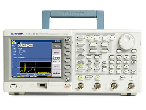
- Arbitrary Function Generator: Tektronix AFG3252C
- 2 Channels
- Wave functions up to 150 MHz
- Sampling rate up to 1 GS/s, 14 bits
- Memory 128K
- Custom high-speed relay: BGI
- DC and battery powered
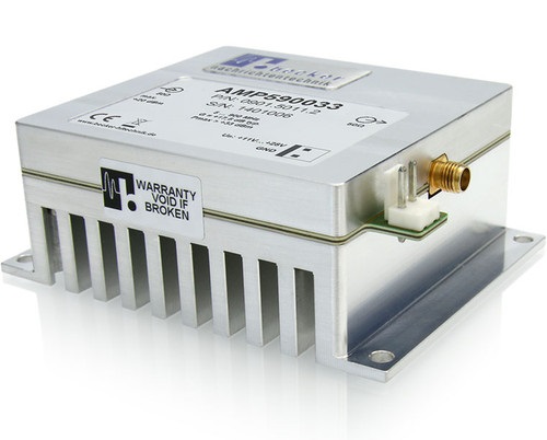
- High-frequency amplifier: AMP590033
- 5 - 900 MHz
- 17.5 dB gain
- Transducer: LiNbO3
- 10 ° and 36 ° Y-cut for P & S-waves, and P-waves, respectively
- Diameter: 2.5 - 4.0 mm (ideally)
- Thickness: variable (e.g. 63 micron)
- Anvil: Fujilloy TF08 or TF05 with TEL 8, 5, 4 or 3 mm. Size: 26 mm (or 1 inch).
NB. It is very important that you mount transducers on multiple anvils before beam time (at your institute) and test them! If this work needs to be done at the station before beam time, you may not get the best results (under time pressure).
III. Acoustic Emissions detection
In situ acoustic emissions detection in the LVP at HPHT conditions is possible using the Acoustic Emissions Detection system at P61B.
This system comprises:
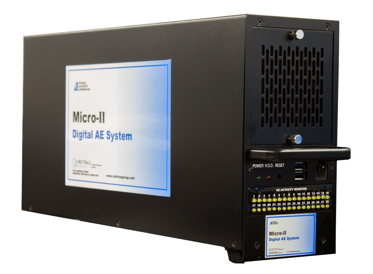
- Measurement system: MISTRAS Micro-II PC
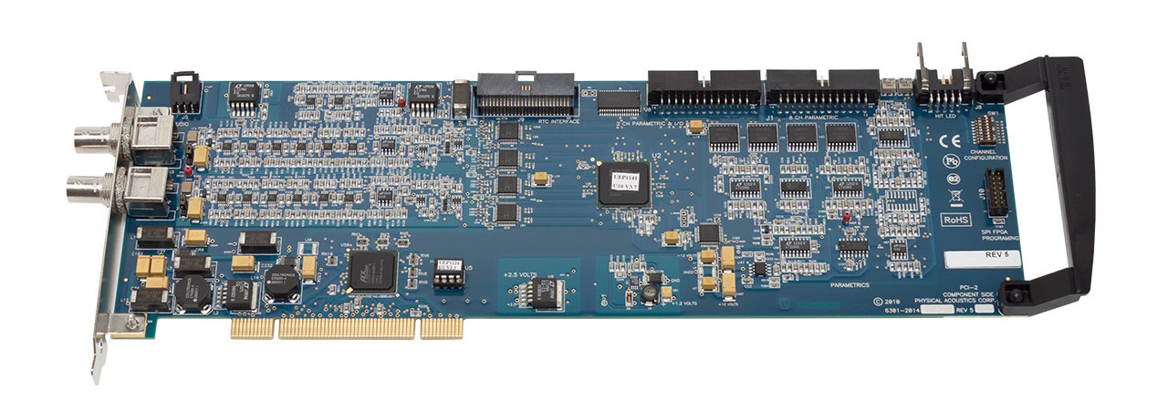
- 6 Channels, 3 PCI-2 cards
- Sampling rate up to 40 MS/s, 18 bits
- Bandwidth: 0.1 - 3 MHz
- Various filters (high-pass, low-pass), thresholds, and gain settings
- Max. signal amplitude: 100 dB
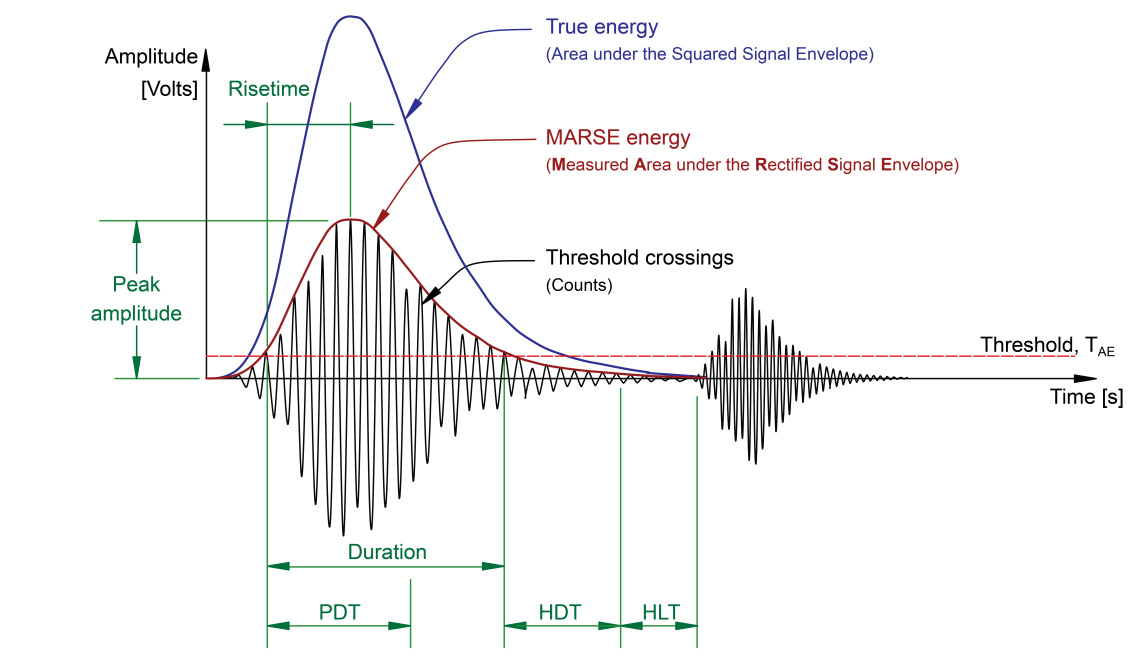
- Full feature AE extraction: Time of 1st Threshold Crossing, Counts to Peak, Peak Amplitude, Signal Strength, Duration, Rise Time, Counts, True Energy, RMS, and ASL
- Preamplifier: MISTRAS 20-40-60
- Gain settings of 20, 40 and 60 dB
- Powered by the AE system via the coaxial cable
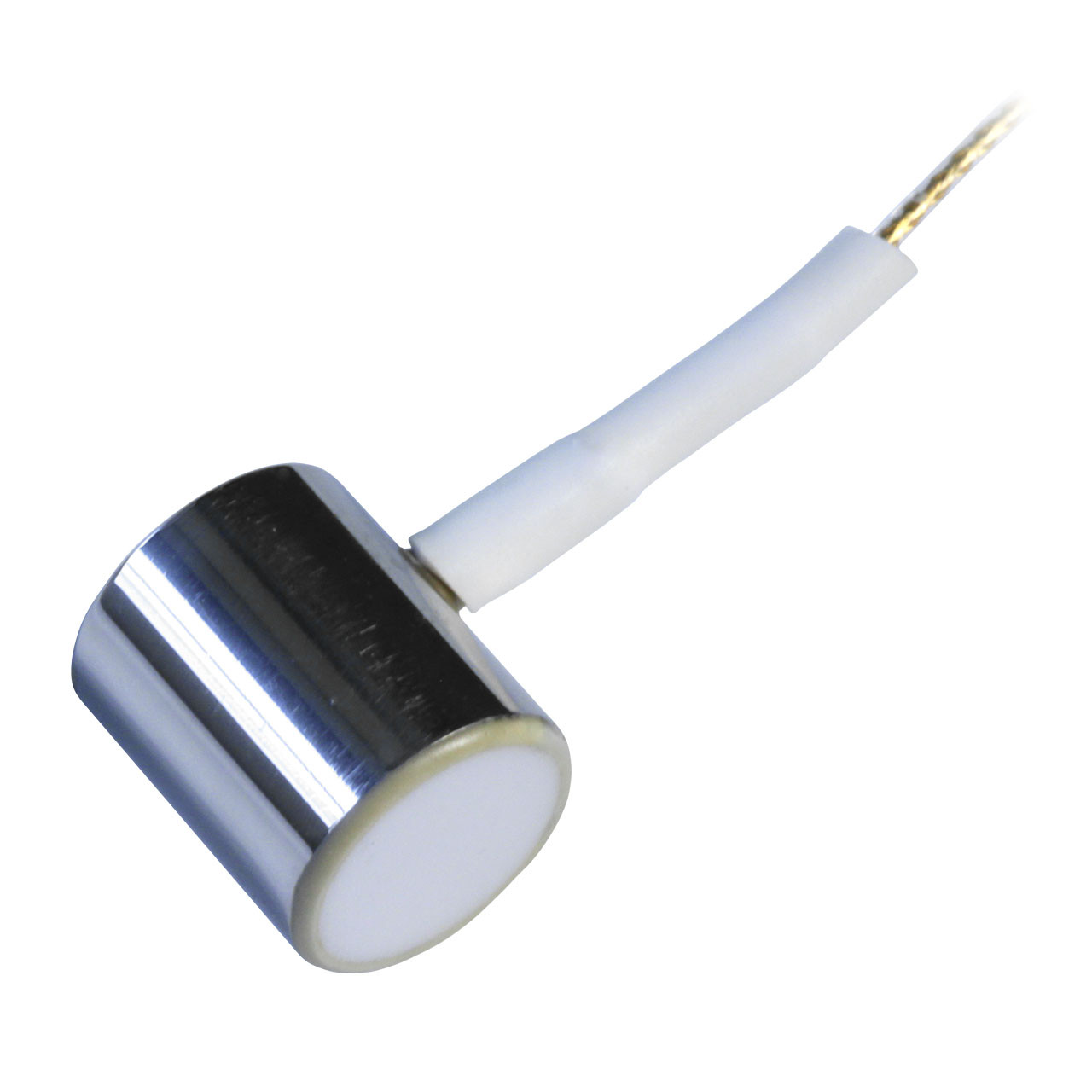
- Sensors: MISTRAS micro-200HF
- Broadband sensor: 0.5 - 4.5 MHz
- Resonance frequency: 2.5 MHz
- Sensitive up to 170 °C
- Diameter = 9.5 mm, height = 11 mm
- Cable length: 30 mm
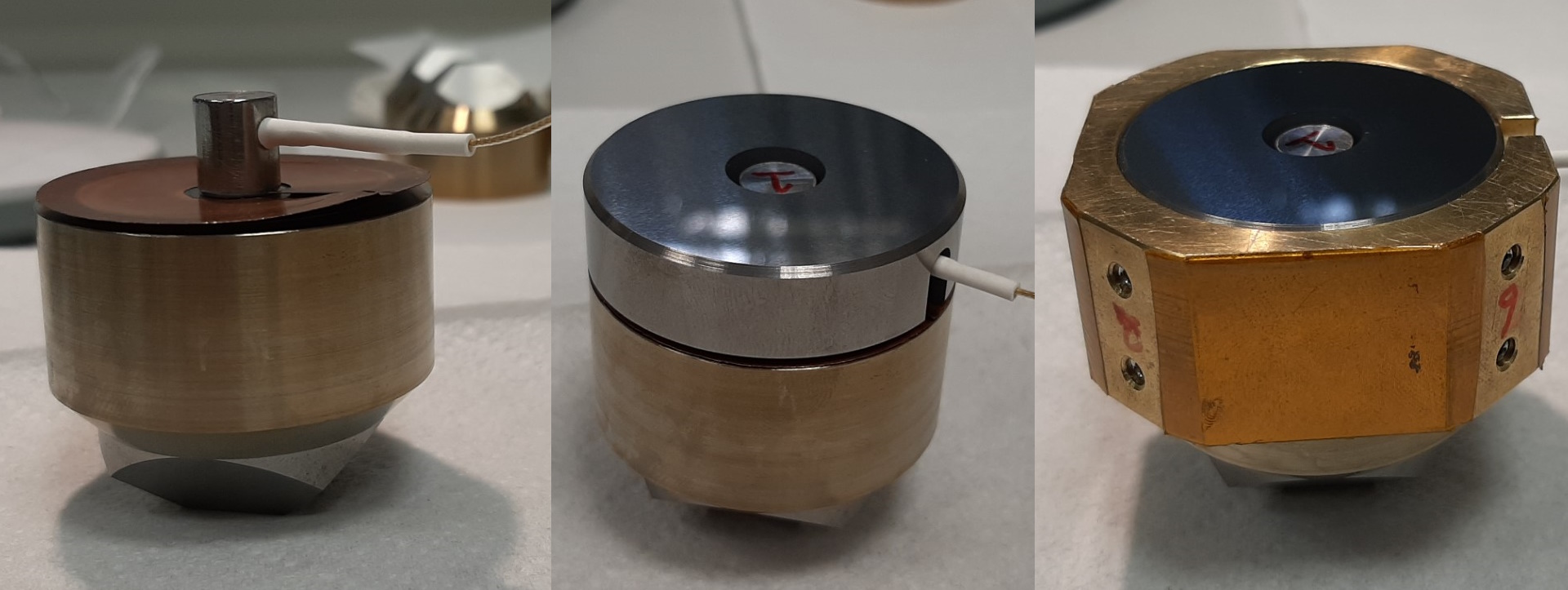
- Sensor mounting on (6) anvils
- 12 mm thick WC support ring
- 32 mm diameter anvils with TEL: 12, 9 and 5 mm
- Max. pressures up to 3, 7 and 10 GPa, respectively.
- AE signal characteristics
NB. If you want to use this system and anvils, please observe the recommendations from the beamline manager (R. Farla), unless you bring your own components. In that case, make sure they are compatible in the LVP!