Figure 2
An almost perfect overlap between the electron and laser beam is essential for the SASE process to take place. As an empirical rule from many simulations it has turned out that an overlap degradation which does not exceed about 20% of the RMS beam size is still tolerable and does not deteriorate the SASE process too much. In this context it is irrelevant if the overlap is disturbed by field errors in the undulator or by mechanical misalignment of quadrupoles. Consequently, this imposes tough requirements on the second field integral of the undulator field, i. e. the beam excursion, as well as on the alignment of the quadrupoles of the FODO lattice.
For Phase 1 of the TTF FEL using a 300 MeV electron beam, the transverse beam size is about 60 µm. The corresponding tolerance on the second field integral corresponds to 12 Tmm2. The quadrupoles have to be aligned with an accuracy of 15 µm. This requires both, the use of highly accurate magnetic measurement techniques and laser interferometry for the mechanical alignment. Field optimization is subdivided into the two steps: First, the "naked" undulator is optimized and error corrected in both transverse directions, i.e. the focusing magnets are not yet attached. Second, the focusing magnet arrays are attached to the pre-optimized undulator and the axes of the quadrupoles are aligned using the techniques described below. Without the focusing magnets the undulator is just like any hybrid undulator. The only minor difference is the larger pole overhang of 2.5 mm at the gap side. The structures were assembled using state of the art sorting and assembling procedures. The horizontal field is measured using a small sensor coil with dimensions 3x5x10 mm3 and 3500 windings and an analog integrator. Using this method the second horizontal field integral of a 4.5 m long structure can be measured with an accuracy of a few Tmm2. The horizontal field errors were small. For their correction between 3 and 14 shims were sufficient.
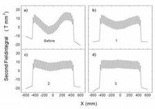
The vertical field has been optimized using "Field Fine Tuning by Pole Height Adjustment". To do so, the mechanical design of the structure has to be such, that all poles are height adjustable using set screws on either side of the poles. In this way they could be moved in and out by a few tenths of a millimeter. The optimization goal is to obtain a perfectly straight trajectory over the whole undulator length. The basic idea of the adjustment method is simple but rather complex to implement for an undulator system with 327 poles as a change of a specific pole affects also the field in its neighbourhood: First, from measured field data the required field correction is calculated. Second, this correction is used to evaluate the required movement of poles. Figure 2 shows the results of the trajectory optimization of the first undulator module.
Figure 2:
Trajectory optimization of the first 4.5 m long undulator module. Note the different scale in a). The results shown in b)-d) have been obtained after three optimization steps
Figure 2a shows the initial second field integral with an RMS value of 192 Tmm2, note the expanded scale. Successively three iterations are shown. The results are self explaining. After the last step an RMS value of 7.1 Tmm2 has been obtained, which is already very close to 6.5 Tmm2 caused by the orbit oscillation anyway. In any case it is well below the required specification of 10 Tmm2. Experience has shown that the first iteration requires by far the most adjustments. Almost every pole has to be tuned. The higher the iteration count the smaller were the required corrections.
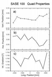
The alignment of the FODO quadrupoles is done using the Rectangular Coil Method (RCM). This method allows for the exact location of the quadrupole center as well as the precise determination of its integrated gradient in the presence of the undulator field. Figure 3 shows the results obtained for the first of the three structures.
Figure 3:
Fine tuning results for the ten FODO quadrupoles of the first undulator segment (SASE100):
a. Vertical center position,
b. Horizontal center position,
c. Integrated gradient.
Vertical and horizontal deviation of the ten quadrupole center positions are shown in Figs. 3a+b.Figure 3c shows the corresponding magnitude of quadrupole strengths. It can be seen that the centers do not deviate more than about ± 53 µm. The strengths do not deviate more than about ± 0.75%. These deviations are acceptable and well within the tuning range of corrector coils (see References for details).


