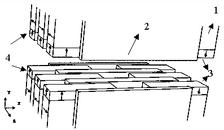
Figure 1:
The Four Magnet Focusing Undulator (4MFU) as an example for a combined function device.
1 : Magnets to generate the dipole like periodic undulator field
2 : Pole pieces
3, 4 : Focusing magnet arrays magnetized parallel / antiparallel to the Y-axis to generate the quadrupolar field
General design considerations for very long undulator systems such as needed for SASE FELs are described in References. The undulator system for the TTF has the following basic parameters:
|
Period length: |
27.3 mm |
|---|---|
|
Gap: |
12 mm |
|
Peak field: |
0.47 T |
|
K parameter: |
1.17 |
The whole magnetic structure is subdivided into three 4.5 m long undulator segments. In front, after and in between two undulator segments diagnostic stations using wire scanners and position monitors are located. The field distributions and the lengths of the interspacings are matched so that the radiation interferes constructively on axis. The total length of the system is more than 15 m. Additional strong focusing is required in any case in order to keep the electron beam size reasonably small over the whole length of the device. A new type of undulator which combines the focusing and the generation of the periodic undulator field has been developped (combined function focusing). This design was mandatory as a consequence of the small value of the optimum β-function of only 1 m inside the undulator. It combines the following properties:
- It is a completely planar structure, which allows for very good access to the field region at the beam position. This is important for high accuracy field measurements but also for inserting the vacuum chamber without breaking magnetic circuits.
- The gradient can be as large as 17 T/m. The exact value of strength and position of the quadrupole axis is fine tunable.
- Undulator and focusing fields are decoupled. This means that on the quadrupole axis the sign and magnitude of the field gradient has no influence on the undulator field and vice versa.
A detailed explanation may be found in References. Here it is described only briefly: Permanent magnet (PM) technology using state of the art NdFeB magnet material has been chosen for the undulator. Figure 1 shows a schematic 3-D view of 1½ periods of the 4MFU principle. It is based on a regular Halbach type hybrid structure, consisting of the magnets creating the undulator field (1) and the poles conducting the flux (2). The gap between the poles is kept fixed at 12 mm. There is no gap tunability needed since the photon wavelength can be tuned by the electron beam energy. In the 2.5 mm recess between magnets and poles the focusing magnet arrays (3), (4) are placed. They are magnetized parallel / antiparallel to the Y-axis as can be seen in Figure 1. Each of the four magnet arrays can be adjusted individually in the horizontal direction. This gives the required adjustabilty of the gradient as well as of the position horizontal and vertical quadrupole center. More details are found in References.


