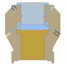
Figure 3: Schematic of the pole height and tilt adjustment by regulation screws, used for the magnetic fine tuning.
The support frame of the 2 m long undulators is a progression of the common development of PETRA III and XFEL prototype undulators, and the mechanical design of the magnetic structure is an advancement of the well-proven concept used for the FLASH undulators. A new design feature, which allows very accurate fine-tuning of the magnetic field, is the possibility to tilt individual poles (up to 2 mrad), in addition to the height adjustment (up to 300 μm) (Fig. 3). For the tuning process, it is important to start with a well-defined initial configuration of the magnet structure. By means of an adjustment gauge with two micro meter dials per pole. The initial pole over hang and tilt are set to the nominal values with high accuracy (10 μm, 0.25 mrad) relative to the non-magnetic support structure.
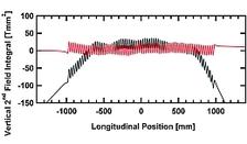
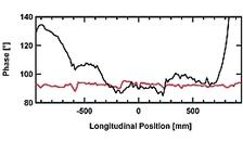
The initial trajectory is scanned by a Hall-probe and residual errors are being assigned to the respective poles for which the necessary pole shift or tilt is calculated. For the vertical field component, an optimization of the local K-parameter is used. It is corrected in each half period of the undulator by shifting the pole vertically, thereby improving the horizontal trajectory as well as the phase shake (Fig. 4) reaching final values of only 1.2° (rms) for the phase shake and 10 Tmm2 (rms) in the second field integral.
In a second step, the vertical trajectory is adjusted by pole tilting. The following adjustment comprises the correction of multi pole components which are probed by wire scans to measure the first and second field integrals. With the extended pole adjustment measures, multipoles can partly also be corrected by pole tuning rather than conventional shimming which is then later applied in addition.
Finally, the end poles of the undulator structure are trimmed to reduce the gap dependency of the first field integral. The residual field integral variations are in the order of 0.1 Tmm over the entire gap range and will be compensated by small air coils.


