


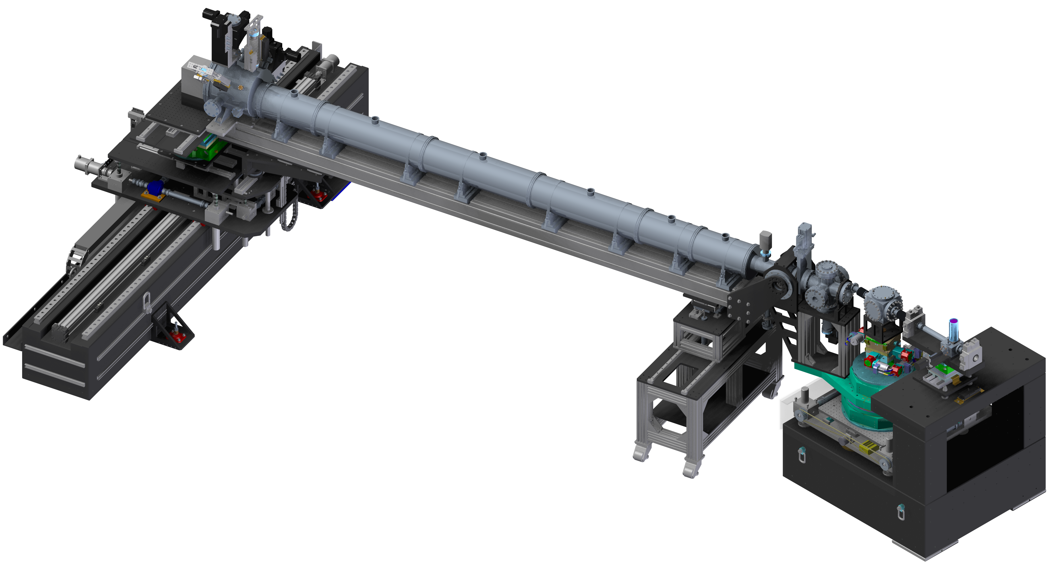
Schematic view of the standard XPCS/CDI setup in EH2.
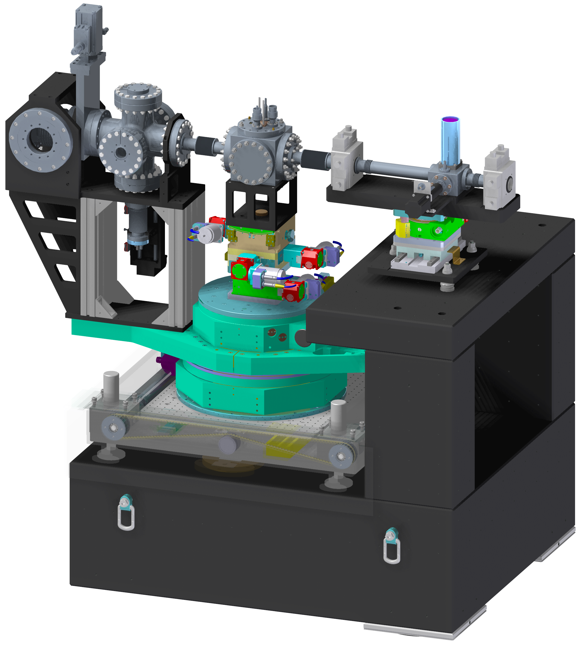
The standard CDI/XPCS setup in EH2 is based on a Huber diffractometer. This diffractometer is mounted on a granite support and can be moved out of the beam path on air pads. The diffractometer is based on a combination of a Huber 440 and 430 goniometer sitting on a YZ translation. For most experiments the 440 goniometer is used as the rotational bearing for the 5 m long detector arm. On top of the goniometers a tower of Huber stages (170x170mm2 size) is mounted. In the typical configuration it offers XYZ translations (XY: Huber 5102.20; Z: Huber 5103.A20-40) as well as a 2-circle segment (Huber 5203.20) for rotations around X & Y. A DN100 (6" flange OD) vacuum cube is used as the standard cell for the sample environment. Examples for different sample cell inserts are displayed when clicking on the navigation button (left side).
For experiments in SAXS geometry, the sample cell is fully vacuum integrated. It is connected along the X-ray beam direction with DN40 (2.75" Flange OD) bellows. Upstream of the sample environment sits a pair of JJ X-Ray slits (IB-C30-HV) on a Huber YZ stage. Between the slits is a vacuum integrated monitor unit. Downstream of the sample environment a 6-way cross (4" tube ID) followed by a DN100 gate valve connects the sample region via a 5 m long flightpath to the detector region.